Netgear GS516TP Software Administration Manual - Page 187
IP Binding Configuration, IP Binding Table
 |
View all Netgear GS516TP manuals
Add to My Manuals
Save this manual to your list of manuals |
Page 187 highlights
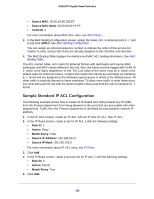
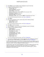
GS516TP Gigabit Smart Switches 6. In the IP Binding Configuration screen, assign ACL ID 1 to the Ethernet ports 2, 3, and 4, and assign a sequence number of 1. See IP Binding Configuration . By default, this IP ACL is bound on the inbound direction, so it examines traffic as it enters the switch. 7. Click APPLY. 8. Use the IP Binding Table screen to view the interfaces and IP ACL binding information. See IP Binding Table . The IP ACL in this example matches all packets with the source IP address and subnet mask of the Finance department network and denies it on the Ethernet interfaces 2, 3, and 4 of the switch. The second rule permits all non-Finance traffic on the ports. The second rule is required because there is an explicit deny all rule as the lowest priority rule. 187
-
 1
1 -
2
-
3
-
4
-
5
-
6
-
7
-
8
-
9
-
10
-
11
-
12
-
13
-
14
-
15
-
16
-
17
-
18
-
19
-
20
-
21
-
22
-
23
-
24
-
25
-
26
-
27
-
28
-
29
-
30
-
31
-
32
-
33
-
34
-
35
-
36
-
37
-
38
-
39
-
40
-
41
-
42
-
43
-
44
-
45
-
46
-
47
-
48
-
49
-
50
-
51
-
52
-
53
-
54
-
55
-
56
-
57
-
58
-
59
-
60
-
61
-
62
-
63
-
64
-
65
-
66
-
67
-
68
-
69
-
70
-
71
-
72
-
73
-
74
-
75
-
76
-
77
-
78
-
79
-
80
-
81
-
82
-
83
-
84
-
85
-
86
-
87
-
88
-
89
-
90
-
91
-
92
-
93
-
94
-
95
-
96
-
97
-
98
-
99
-
100
-
101
-
102
-
103
-
104
-
105
-
106
-
107
-
108
-
109
-
110
-
111
-
112
-
113
-
114
-
115
-
116
-
117
-
118
-
119
-
120
-
121
-
122
-
123
-
124
-
125
-
126
-
127
-
128
-
129
-
130
-
131
-
132
-
133
-
134
-
135
-
136
-
137
-
138
-
139
-
140
-
141
-
142
-
143
-
144
-
145
-
146
-
147
-
148
-
149
-
150
-
151
-
152
-
153
-
154
-
155
-
156
-
157
-
158
-
159
-
160
-
161
-
162
-
163
-
164
-
165
-
166
-
167
-
168
-
169
-
170
-
171
-
172
-
173
-
174
-
175
-
176
-
177
-
178
-
179
-
180
-
181
-
 182
182 -
 183
183 -
 184
184 -
 185
185 -
 186
186 -
 187
187 -
 188
188 -
 189
189 -
 190
190 -
 191
191 -
 192
192 -
193
-
194
-
195
-
196
-
197
-
198
-
199
-
200
-
201
-
202
-
203
-
204
-
205
-
206
-
207
-
208
 |
 |
