Epson SureColor S70675 User Manual - Page 125
Using high pressure rollers
 |
View all Epson SureColor S70675 manuals
Add to My Manuals
Save this manual to your list of manuals |
Page 125 highlights
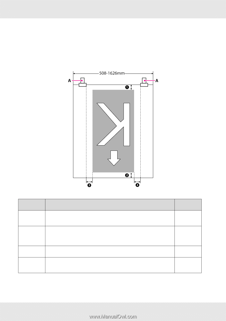
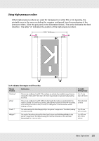
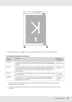
Using high pressure rollers When high pressure rollers are used for transparent or white film or ink layering, the printable area is the area excluding the margins configured from the positioning of the pressure rollers. (See the gray area in the illustration below.) The arrow indicates the feed direction. The letter "A" indicates the position of the high pressure rollers. 1 to 4 indicates the margins on all four sides. Margin Position 1 Bottom1 2 Top1 3 Left2, 3 4 Right2, 3 Explanation This can be configured in a RIP. If the settings are outside the available range, they are changed to 5 mm and 17 mm (0.2 to 0.7 inch) respectively to maintain media feeding accuracy. This can be configured in a RIP. Differs by the length the media was pulled when the media is loaded. For continuous printing, although the margins set in the RIP are added, if the setting is less than 5 mm (0.2 inch), it is changed to 5 mm to maintain media feeding accuracy. The value selected for Side Margin(Left) in the printer's setup menu. The default setting is 5 mm (0.2 inch). The total of the values selected for Print Start Position and Side Margin(Right) in the printer's setup menu. The default setting for Print Start Position is 0 mm and Side Margin(Right) is 5 mm (0.2 inch). Available Setting Range 5 to 17 mm (0.2 to 0.7 inch) 5 mm (0.2 inch) or more 3 to 25 mm (0.1 to 1 inch) 3 to 825 mm (0.1 to 32.5 inches) Basic Operations 125
-
 1
1 -
2
-
3
-
4
-
5
-
6
-
7
-
8
-
9
-
10
-
11
-
12
-
13
-
14
-
15
-
16
-
17
-
18
-
19
-
20
-
21
-
22
-
23
-
24
-
25
-
26
-
27
-
28
-
29
-
30
-
31
-
32
-
33
-
34
-
35
-
36
-
37
-
38
-
39
-
40
-
41
-
42
-
43
-
44
-
45
-
46
-
47
-
48
-
49
-
50
-
51
-
52
-
53
-
54
-
55
-
56
-
57
-
58
-
59
-
60
-
61
-
62
-
63
-
64
-
65
-
66
-
67
-
68
-
69
-
70
-
71
-
72
-
73
-
74
-
75
-
76
-
77
-
78
-
79
-
80
-
81
-
82
-
83
-
84
-
85
-
86
-
87
-
88
-
89
-
90
-
91
-
92
-
93
-
94
-
95
-
96
-
97
-
98
-
99
-
100
-
101
-
102
-
103
-
104
-
105
-
106
-
107
-
108
-
109
-
110
-
111
-
112
-
113
-
114
-
115
-
116
-
117
-
118
-
119
-
 120
120 -
 121
121 -
 122
122 -
 123
123 -
 124
124 -
 125
125 -
 126
126 -
 127
127 -
 128
128 -
 129
129 -
 130
130 -
131
-
132
-
133
-
134
-
135
-
136
-
137
-
138
-
139
-
140
-
141
-
142
-
143
-
144
-
145
-
146
-
147
-
148
-
149
-
150
-
151
-
152
-
153
-
154
-
155
-
156
-
157
-
158
-
159
-
160
-
161
-
162
-
163
-
164
-
165
-
166
-
167
-
168
-
169
-
170
-
171
-
172
-
173
-
174
-
175
-
176
-
177
-
178
-
179
-
180
-
181
-
182
-
183
-
184
-
185
-
186
-
187
-
188
-
189
-
190
-
191
-
192
-
193
-
194
-
195
-
196
-
197
-
198
-
199
-
200
-
201
-
202
-
203
-
204
-
205
-
206
-
207
-
208
-
209
-
210
-
211
-
212
-
213
-
214
-
215
-
216
-
217
-
218
-
219
-
220
-
221
-
222
-
223
-
224
-
225
-
226
-
227
-
228
-
229
-
230
-
231
-
232
-
233
-
234
-
235
-
236
-
237
-
238
-
239
-
240
-
241
-
242
-
243
-
244
-
245
-
246
-
247
-
248
-
249
-
250
-
251
-
252
-
253
-
254
-
255
 |
 |