HP 6125XLG R2306-HP 6125XLG Blade Switch Fundamentals Configuration Guide - Page 62
Network requirements, Configuration procedure, Enable Telnet server.
 |
View all HP 6125XLG manuals
Add to My Manuals
Save this manual to your list of manuals |
Page 62 highlights
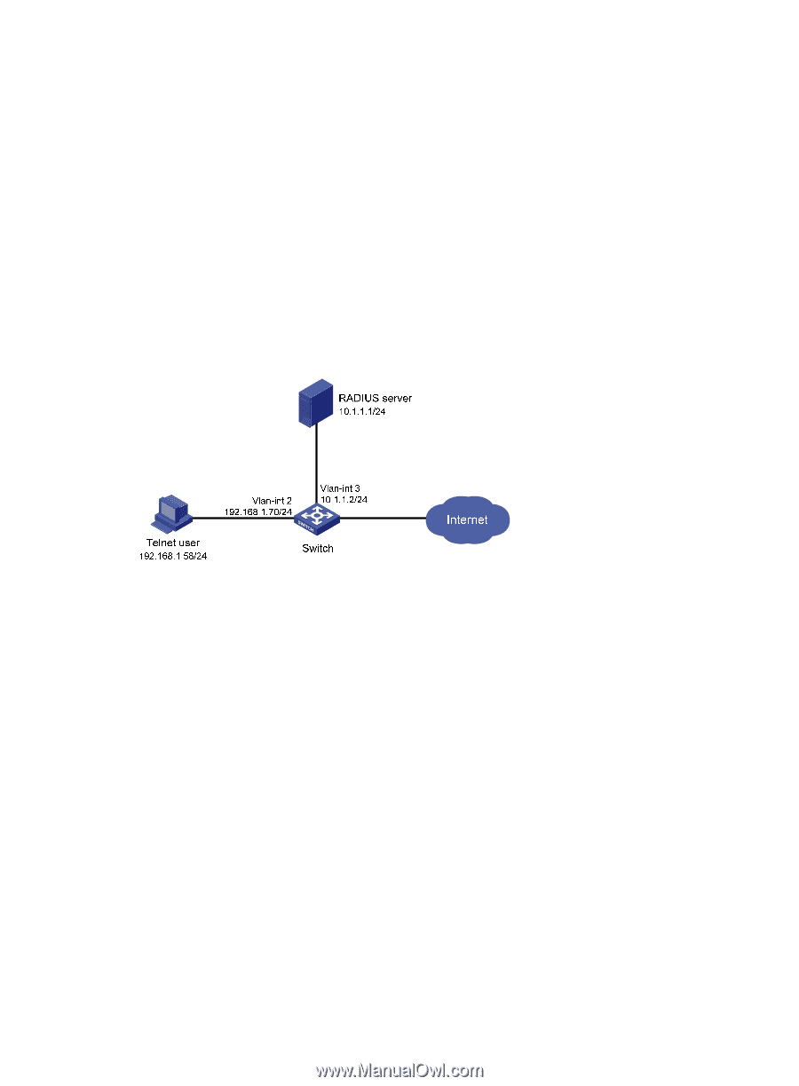
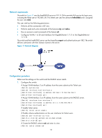
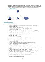
Network requirements The switch in Figure 17 uses the FreeRADIUS server at 10.1.1.1/24 to provide AAA service for login users, including the Telnet user at 192.168.1.58. This Telnet user uses the username hello@bbb and is assigned the user role role2. This user role has the following permissions: • Performs all the commands in ISP view. • Performs read and write commands of the features arp and radius. • Has no access to read commands of the feature acl. • Configures VLANs 1 to 20 and interfaces Ten-GigabitEthernet 1/1/5 to Ten-GigabitEthernet 1/1/10. The switch and the FreeRADIUS server use the shared key expert and authentication port 1812. The switch delivers usernames with their domain names to the server. Figure 17 Network diagram Configuration procedure Make sure the settings on the switch and the RADIUS server match. 1. Configure the switch: # Assign VLAN-interface 2 an IP address from the same subnet as the Telnet user. system-view [Switch] interface vlan-interface 2 [Switch-Vlan-interface2] ip address 192.168.1.70 255.255.255.0 [Switch-Vlan-interface2] quit # Assign VLAN-interface 3 an IP address from the same subnet as the RADIUS server. [Switch] interface vlan-interface 3 [Switch-Vlan-interface3] ip address 10.1.1.2 255.255.255.0 [Switch-Vlan-interface3] quit # Enable Telnet server. [Switch] telnet server enable # Enable scheme authentication on the user interfaces for Telnet users. [Switch] user-interface vty 0 15 [Switch-ui-vty0-15] authentication-mode scheme [Switch-ui-vty0-15] quit # Create the RADIUS scheme rad and enter its view. [Switch] radius scheme rad 55
-
 1
1 -
2
-
3
-
4
-
5
-
6
-
7
-
8
-
9
-
10
-
11
-
12
-
13
-
14
-
15
-
16
-
17
-
18
-
19
-
20
-
21
-
22
-
23
-
24
-
25
-
26
-
27
-
28
-
29
-
30
-
31
-
32
-
33
-
34
-
35
-
36
-
37
-
38
-
39
-
40
-
41
-
42
-
43
-
44
-
45
-
46
-
47
-
48
-
49
-
50
-
51
-
52
-
53
-
54
-
55
-
56
-
 57
57 -
 58
58 -
 59
59 -
 60
60 -
 61
61 -
 62
62 -
 63
63 -
 64
64 -
 65
65 -
 66
66 -
 67
67 -
68
-
69
-
70
-
71
-
72
-
73
-
74
-
75
-
76
-
77
-
78
-
79
-
80
-
81
-
82
-
83
-
84
-
85
-
86
-
87
-
88
-
89
-
90
-
91
-
92
-
93
-
94
-
95
-
96
-
97
-
98
-
99
-
100
-
101
-
102
-
103
-
104
-
105
-
106
-
107
-
108
-
109
-
110
-
111
-
112
-
113
-
114
-
115
-
116
-
117
-
118
-
119
-
120
-
121
-
122
-
123
-
124
-
125
-
126
-
127
-
128
-
129
-
130
-
131
-
132
-
133
-
134
-
135
-
136
-
137
-
138
-
139
-
140
-
141
-
142
-
143
-
144
-
145
-
146
-
147
-
148
-
149
-
150
-
151
-
152
-
153
-
154
-
155
 |
 |