IBM 2170275 Reference Guide - Page 106
Align the drive bay with the notch., Pivot the drive bay toward the housing until
 |
View all IBM 2170275 manuals
Add to My Manuals
Save this manual to your list of manuals |
Page 106 highlights
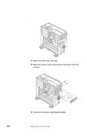
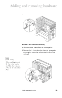
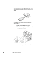
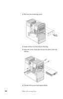
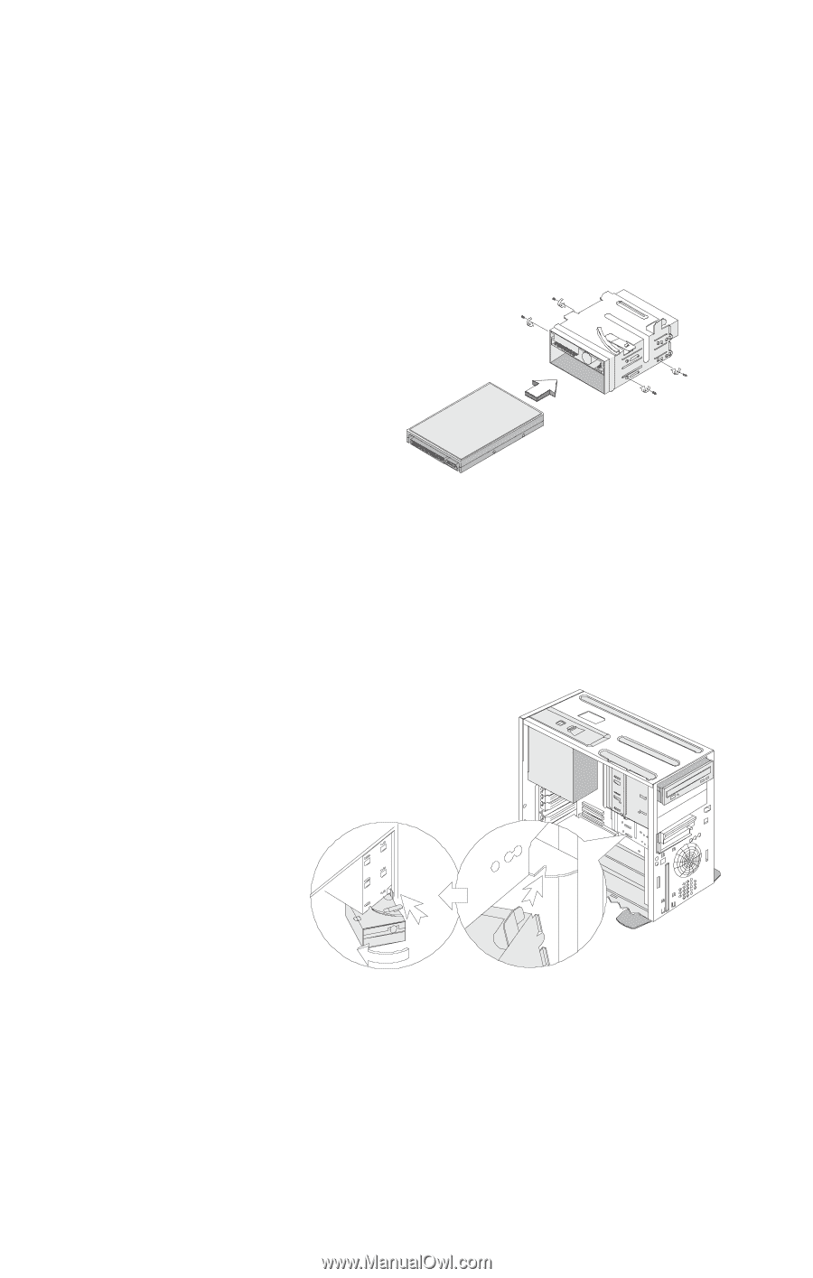
3 From the back of the drive bay, carefully insert a 3.5inch disk drive then secure it with four screws on the sides. 4 Re-install the drive bay into the housing as in the following figure: a Align the drive bay with the notch. b Pivot the drive bay toward the housing until the tab clicks into place. . 5 Connect the signal and power cables to the drives. 102 Adding and removing drives
-
 1
1 -
2
-
3
-
4
-
5
-
6
-
7
-
8
-
9
-
10
-
11
-
12
-
13
-
14
-
15
-
16
-
17
-
18
-
19
-
20
-
21
-
22
-
23
-
24
-
25
-
26
-
27
-
28
-
29
-
30
-
31
-
32
-
33
-
34
-
35
-
36
-
37
-
38
-
39
-
40
-
41
-
42
-
43
-
44
-
45
-
46
-
47
-
48
-
49
-
50
-
51
-
52
-
53
-
54
-
55
-
56
-
57
-
58
-
59
-
60
-
61
-
62
-
63
-
64
-
65
-
66
-
67
-
68
-
69
-
70
-
71
-
72
-
73
-
74
-
75
-
76
-
77
-
78
-
79
-
80
-
81
-
82
-
83
-
84
-
85
-
86
-
87
-
88
-
89
-
90
-
91
-
92
-
93
-
94
-
95
-
96
-
97
-
98
-
99
-
100
-
 101
101 -
 102
102 -
 103
103 -
 104
104 -
 105
105 -
 106
106 -
 107
107 -
 108
108 -
 109
109 -
 110
110 -
 111
111 -
112
-
113
-
114
-
115
-
116
-
117
-
118
-
119
-
120
-
121
 |
 |
102
Adding and removing drives
3
From the back of the drive bay, carefully insert a 3.5-
inch disk drive then secure it with four screws on the
sides.
4
Re-install the drive bay into the housing as in the
following figure:
a
Align the drive bay with the notch.
b
Pivot the drive bay toward the housing until
the tab clicks into place.
.
5
Connect the signal and power cables to the drives.