Cisco RV042 User Guide - Page 74
Appendix D: IPSec NAT Traversal, Overview, Before You Begin, Configuration of Scenario 1, Appendix D - one to one nat
 |
UPC - 745883560530
View all Cisco RV042 manuals
Add to My Manuals
Save this manual to your list of manuals |
Page 74 highlights
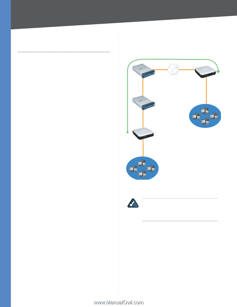
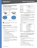
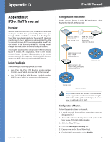
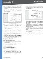
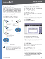
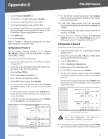
Appendix D IPSec NAT Traversal Appendix D: IPSec NAT Traversal Overview Network Address Translation (NAT) traversal is a technique developed so that data protected by IPSec can pass through a NAT. (See NAT 1 and NAT 2 in the diagram.) Since IPSec provides integrity for the entire IP datagram, any changes to the IP addressing will invalidate the data. To resolve this issue, NAT traversal appends a new IP and UDP header to the incoming datagram, ensuring that no changes are made to the incoming datagram stream. This chapter discusses two scenarios. In the first scenario, Router A initiates IKE negotiation, while in the second scenario, Router B initiates IKE negotiation. In the second scenario, since the IKE responder is behind a NAT device, a one-to-one NAT rule is required on the NAT device. Before You Begin The following is a list of equipment you need: •• Two 4-Port SSL/IPSec VPN Routers (model number: RVL200), one of which is connected to the Internet •• Two 10/100 4-Port VPN Routers (model number: RV042), one of which is connected to the Internet 10/100 4-Port VPN Router Configuration of Scenario 1 In this scenario, Router A is the RVL200 Initiator, while Router B is the RVL200 Responder. WAN: 192.168.99.11 NAT 2 - RV042 LAN: 192.168.111.1 WAN: 192.168.99.22 Router B - RVL200 Responder LAN: 192.168.2.0/24 WAN: 192.168.111.101 NAT 1 - RV042 LAN: 192.168.11.1 WAN: 192.168.11.101 Router A - RVL200 Initiator LAN: 192.168.1.0/24 192.168.2.100 192.168.1.101 Traffic in Scenario 1 NOTE: Both the IPSec initiator and responder must support the mechanism for detecting the NAT router in the path and changing to a new port, as defined in RFC 3947. Configuration of Router A Follow these instructions for Router A. 1. Launch the web browser for a networked computer, designated PC 1. 2. Access the web-based utility of Router A. (Refer to the User Guide of the RVL200 for details.) 3. Click the IPSec VPN tab. 4. Click the Gateway to Gateway tab. 5. Enter a name in the Tunnel Name field. 6. For the VPN Tunnel setting, select Enable. 67
-
 1
1 -
2
-
3
-
4
-
5
-
6
-
7
-
8
-
9
-
10
-
11
-
12
-
13
-
14
-
15
-
16
-
17
-
18
-
19
-
20
-
21
-
22
-
23
-
24
-
25
-
26
-
27
-
28
-
29
-
30
-
31
-
32
-
33
-
34
-
35
-
36
-
37
-
38
-
39
-
40
-
41
-
42
-
43
-
44
-
45
-
46
-
47
-
48
-
49
-
50
-
51
-
52
-
53
-
54
-
55
-
56
-
57
-
58
-
59
-
60
-
61
-
62
-
63
-
64
-
65
-
66
-
67
-
68
-
 69
69 -
 70
70 -
 71
71 -
 72
72 -
 73
73 -
 74
74 -
 75
75 -
 76
76 -
 77
77 -
 78
78 -
 79
79 -
80
-
81
-
82
-
83
-
84
-
85
-
86
-
87
-
88
-
89
-
90
-
91
-
92
-
93
-
94
-
95
-
96
-
97
-
98
-
99
-
100
-
101
-
102
-
103
 |
 |