Yamaha 02R96 Owner's Manual - Page 123
Surround Pan, Bus Routing, Meters, Group, On/off, Fader, To St Pan, On/off & Fader
 |
View all Yamaha 02R96 manuals
Add to My Manuals
Save this manual to your list of manuals |
Page 123 highlights
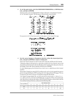
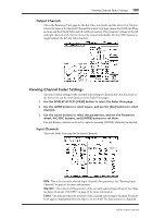
110 Chapter 11-Common Channel Functions numerically below the fader. See "Setting Input Channel Levels" on page 65 for more information. SURROUND PAN: The Surround pan parameters for the currently selected Input Channel are displayed only when a Surround mode other than Stereo is selected. See "Using Surround Pan" on page 69 for more information. BUS ROUTING: This section contains Routing and Follow Pan buttons for the currently selected Input Channel. See "Routing Input Channels" on page 66 for more information. The Direct Out output patch can also be set. See "Patching Direct Outs" on page 56 for more information. AUX: These are the currently selected Input Channel's Aux Send Level, On/Off, and Pre/Post parameters. While a rotary control is selected, the Aux Send can be turned on and off by pressing [ENTER]. See "Aux Sends" on page 79 for more information. Meters: These meters indicate the levels of the currently selected Input Channel and its horizontal or vertical partner. The metering position is displayed below them. GROUP: These buttons indicate which Fader, Mute, EQ, or Comp group, if any, the currently selected Input Channel is in. Bus Outs This is the Fader View page for the Bus Outs. ON/OFF: This is the On/Off parameter of the currently selected Bus Out. See "Muting Bus Outs (ON/OFF)" on page 77 for more information. Fader: This indicates the fader position of the currently selected Bus Out. The fader knob appears highlighted when the fader is set to 0.0 dB. The fader position is displayed numerically below the fader. See "Setting Bus Out Levels" on page 77 for more information. TO ST PAN, ON/OFF & Fader: These are the Bus Out to Stereo Out Pan, On/Off, and Fader parameters for the currently selected Bus Out. The fader knob appears highlighted when the fader is set to 0.0 dB. The fader position is displayed numerically below the fader. See "Sending Bus Outs to the Stereo Out" on page 78 for more information. Meters: These meters indicate the levels of the currently selected Bus Out and its partner. The metering position is displayed below them. GROUP: These buttons indicate which Fader, Mute, EQ, or Comp group, if any, the currently selected Bus Out is in. 02R96-Owner's Manual
-
 1
1 -
2
-
3
-
4
-
5
-
6
-
7
-
8
-
9
-
10
-
11
-
12
-
13
-
14
-
15
-
16
-
17
-
18
-
19
-
20
-
21
-
22
-
23
-
24
-
25
-
26
-
27
-
28
-
29
-
30
-
31
-
32
-
33
-
34
-
35
-
36
-
37
-
38
-
39
-
40
-
41
-
42
-
43
-
44
-
45
-
46
-
47
-
48
-
49
-
50
-
51
-
52
-
53
-
54
-
55
-
56
-
57
-
58
-
59
-
60
-
61
-
62
-
63
-
64
-
65
-
66
-
67
-
68
-
69
-
70
-
71
-
72
-
73
-
74
-
75
-
76
-
77
-
78
-
79
-
80
-
81
-
82
-
83
-
84
-
85
-
86
-
87
-
88
-
89
-
90
-
91
-
92
-
93
-
94
-
95
-
96
-
97
-
98
-
99
-
100
-
101
-
102
-
103
-
104
-
105
-
106
-
107
-
108
-
109
-
110
-
111
-
112
-
113
-
114
-
115
-
116
-
117
-
 118
118 -
 119
119 -
 120
120 -
 121
121 -
 122
122 -
 123
123 -
 124
124 -
 125
125 -
 126
126 -
 127
127 -
 128
128 -
129
-
130
-
131
-
132
-
133
-
134
-
135
-
136
-
137
-
138
-
139
-
140
-
141
-
142
-
143
-
144
-
145
-
146
-
147
-
148
-
149
-
150
-
151
-
152
-
153
-
154
-
155
-
156
-
157
-
158
-
159
-
160
-
161
-
162
-
163
-
164
-
165
-
166
-
167
-
168
-
169
-
170
-
171
-
172
-
173
-
174
-
175
-
176
-
177
-
178
-
179
-
180
-
181
-
182
-
183
-
184
-
185
-
186
-
187
-
188
-
189
-
190
-
191
-
192
-
193
-
194
-
195
-
196
-
197
-
198
-
199
-
200
-
201
-
202
-
203
-
204
-
205
-
206
-
207
-
208
-
209
-
210
-
211
-
212
-
213
-
214
-
215
-
216
-
217
-
218
-
219
-
220
-
221
-
222
-
223
-
224
-
225
-
226
-
227
-
228
-
229
-
230
-
231
-
232
-
233
-
234
-
235
-
236
-
237
-
238
-
239
-
240
-
241
-
242
-
243
-
244
-
245
-
246
-
247
-
248
-
249
-
250
-
251
-
252
-
253
-
254
-
255
-
256
-
257
-
258
-
259
-
260
-
261
-
262
-
263
-
264
-
265
-
266
-
267
-
268
-
269
-
270
-
271
-
272
-
273
-
274
-
275
-
276
-
277
-
278
-
279
-
280
-
281
-
282
-
283
-
284
-
285
-
286
-
287
-
288
-
289
-
290
-
291
-
292
-
293
-
294
-
295
-
296
-
297
-
298
-
299
-
300
-
301
-
302
-
303
-
304
-
305
-
306
-
307
-
308
-
309
-
310
-
311
-
312
-
313
-
314
-
315
 |
 |
