Yamaha 02R96 Owner's Manual - Page 24
Selected Channel
 |
View all Yamaha 02R96 manuals
Add to My Manuals
Save this manual to your list of manuals |
Page 24 highlights
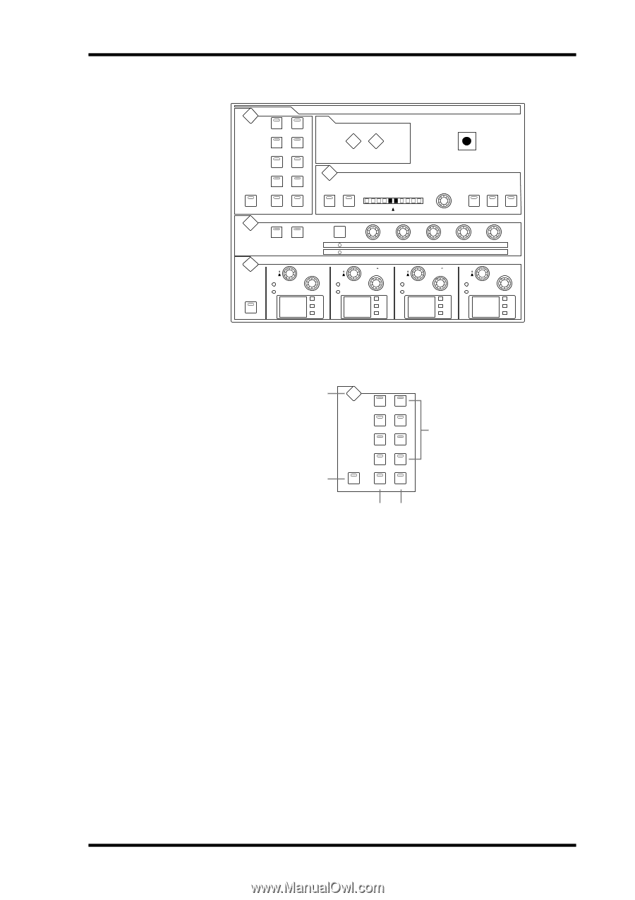
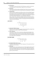
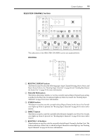
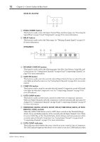
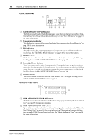
Control Surface 11 SELECTED CHANNEL Section ROUTING DISPLAY 1 2 SELECTED CHANNEL DISPLAY ACCESS 3 4 5 6 7 8 PHASE / DELAY INSERT PAN / SURROUND DISPLAY FOLLOW PAN STEREO DIRECT DYNAMICS L R L ODD R EVEN LINK GRAB EFFECT DISPLAY GATE ON COMP ON EQUALIZER DISPLAY LOW GATE / COMP GATE COMP THRESHOLD THRESHOLD LOW MID EQ ON FREQUENCY Q 125 GAIN dB Hz kHz FREQUENCY Q GAIN dB 1.00 Hz kHz RANGE RATIO ATTACK ATTACK DECAY RELEASE HOLD GAIN HIGH MID HIGH FREQUENCY Q 4.00 GAIN dB Hz kHz FREQUENCY Q GAIN dB 10.0 Hz kHz The subsections of the SELECTED CHANNEL section are explained below. ROUTING 1 ROUTING DISPLAY 1 2 3 4 5 6 2 7 8 FOLLOW PAN STEREO DIRECT 34 5 A ROUTING DISPLAY button This button is used to select the following pages: Input Channel Routing, Bus to Stereo, and Bus to Stereo Library. See "Routing Input Channels" on page 66 and "Sending Bus Outs to the Stereo Out" on page 78 for more information. B FOLLOW PAN button This button determines whether or not the currently selected Input Channel's pan setting is applied to the Bus Outs. Its indicator lights up when it's pressed. See "Routing Input Channels" on page 66 for more information. C STEREO button This button is used to route the currently selected Input Channel to the Stereo Out. Its indicator lights up when it's pressed. See "Routing Input Channels" on page 66 for more information. D DIRECT button This button is used to route the currently selected Input Channel to its Direct Out. Its indicator lights up when it's pressed. See "Routing Input Channels" on page 66 for more information. E ROUTING 1-8 buttons These buttons are used to route the currently selected Input Channel to the Bus Outs. The button indicators of Bus Outs to which the Input Channel is routed light up. See "Routing Input Channels" on page 66 for more information. 02R96-Owner's Manual
-
 1
1 -
2
-
3
-
4
-
5
-
6
-
7
-
8
-
9
-
10
-
11
-
12
-
13
-
14
-
15
-
16
-
17
-
18
-
 19
19 -
 20
20 -
 21
21 -
 22
22 -
 23
23 -
 24
24 -
 25
25 -
 26
26 -
 27
27 -
 28
28 -
 29
29 -
30
-
31
-
32
-
33
-
34
-
35
-
36
-
37
-
38
-
39
-
40
-
41
-
42
-
43
-
44
-
45
-
46
-
47
-
48
-
49
-
50
-
51
-
52
-
53
-
54
-
55
-
56
-
57
-
58
-
59
-
60
-
61
-
62
-
63
-
64
-
65
-
66
-
67
-
68
-
69
-
70
-
71
-
72
-
73
-
74
-
75
-
76
-
77
-
78
-
79
-
80
-
81
-
82
-
83
-
84
-
85
-
86
-
87
-
88
-
89
-
90
-
91
-
92
-
93
-
94
-
95
-
96
-
97
-
98
-
99
-
100
-
101
-
102
-
103
-
104
-
105
-
106
-
107
-
108
-
109
-
110
-
111
-
112
-
113
-
114
-
115
-
116
-
117
-
118
-
119
-
120
-
121
-
122
-
123
-
124
-
125
-
126
-
127
-
128
-
129
-
130
-
131
-
132
-
133
-
134
-
135
-
136
-
137
-
138
-
139
-
140
-
141
-
142
-
143
-
144
-
145
-
146
-
147
-
148
-
149
-
150
-
151
-
152
-
153
-
154
-
155
-
156
-
157
-
158
-
159
-
160
-
161
-
162
-
163
-
164
-
165
-
166
-
167
-
168
-
169
-
170
-
171
-
172
-
173
-
174
-
175
-
176
-
177
-
178
-
179
-
180
-
181
-
182
-
183
-
184
-
185
-
186
-
187
-
188
-
189
-
190
-
191
-
192
-
193
-
194
-
195
-
196
-
197
-
198
-
199
-
200
-
201
-
202
-
203
-
204
-
205
-
206
-
207
-
208
-
209
-
210
-
211
-
212
-
213
-
214
-
215
-
216
-
217
-
218
-
219
-
220
-
221
-
222
-
223
-
224
-
225
-
226
-
227
-
228
-
229
-
230
-
231
-
232
-
233
-
234
-
235
-
236
-
237
-
238
-
239
-
240
-
241
-
242
-
243
-
244
-
245
-
246
-
247
-
248
-
249
-
250
-
251
-
252
-
253
-
254
-
255
-
256
-
257
-
258
-
259
-
260
-
261
-
262
-
263
-
264
-
265
-
266
-
267
-
268
-
269
-
270
-
271
-
272
-
273
-
274
-
275
-
276
-
277
-
278
-
279
-
280
-
281
-
282
-
283
-
284
-
285
-
286
-
287
-
288
-
289
-
290
-
291
-
292
-
293
-
294
-
295
-
296
-
297
-
298
-
299
-
300
-
301
-
302
-
303
-
304
-
305
-
306
-
307
-
308
-
309
-
310
-
311
-
312
-
313
-
314
-
315
 |
 |