Yamaha 02R96 Owner's Manual - Page 19
Yamaha 02R96 Manual
 |
View all Yamaha 02R96 manuals
Add to My Manuals
Save this manual to your list of manuals |
Page 19 highlights
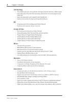
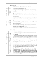
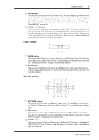
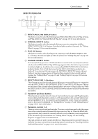
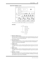
6 Chapter 2-Control Surface & Rear Panel D SOLO buttons These buttons are used to solo Channels. The [SOLO] button indicators of channels that are soloed light up. See "Soloing Channels" on page 102 for more information. E ON buttons These buttons are used to mute Input and Output Channels. Their exact operation depends on the currently selected Layer. The [ON] button indicators of channels that are on light up. F Channel faders These 100 mm touch-sensitive motorized faders are used to set the levels of Input Channels, Bus Outs, and Aux Sends. Their exact operation depends on the currently selected Fader mode and Layer. See "Selecting Fader Modes" on page 35 for more information. Faders can be grouped for simultaneous operation. See "Grouping Input Channel Faders" on page 65 and "Grouping Output Channel Faders" on page 106 for more information. Faders can also be used to select Input and Output Channels. See "Auto Channel Select & Touch Sense Select" on page 34 for more information. They can also be used to punch channels in and out during Automix recording. See "Punching In & Out Individual Parameters" on page 156 for more information. AUX SELECT 1 AUX SELECT DISPLAY AUX 1 AUX 2 AUX 3 AUX 4 AUX 5 AUX 6 AUX 7 AUX 8 2 A AUX SELECT DISPLAY button This button is used to select the following pages: Aux Send, Aux Send Pan, and Input Channel Aux View. See "Aux Sends" on page 79 for more information. B AUX 1-8 buttons These buttons are used to select Aux Sends when sending Input Channel signals to Aux Sends. The button indicator of the currently selected Aux Send lights up. If the currently selected Aux Send is paired, the indicator of its partner flashes. See "Aux Sends" on page 79 for more information. These buttons can also be used to pair Aux Sends. See "Pairing Channels" on page 104 for more information. ENCODER MODE 1 ENCODER MODE DISPLAY PAN AUX ASSIGN 1 ASSIGN 2 23 4 A ENCODER MODE DISPLAY button This button is used to select the Encoder Mode Assign page. See "Selecting Encoder Modes" on page 36 for more information. B PAN button This button is used to select the Pan Encoder mode. Its indicator lights up when this mode is selected. In this mode, the Encoders function as Pan controls while an Input Channel Layer is selected. While the Master Layer is selected, Encoders 1-8 function as Input Channel 49-56 Pan controls, and Encoders 9-24 are inactive. See "Selecting Encoder Modes" on page 36 for more information. 02R96-Owner's Manual
-
 1
1 -
2
-
3
-
4
-
5
-
6
-
7
-
8
-
9
-
10
-
11
-
12
-
13
-
 14
14 -
 15
15 -
 16
16 -
 17
17 -
 18
18 -
 19
19 -
 20
20 -
 21
21 -
 22
22 -
 23
23 -
 24
24 -
25
-
26
-
27
-
28
-
29
-
30
-
31
-
32
-
33
-
34
-
35
-
36
-
37
-
38
-
39
-
40
-
41
-
42
-
43
-
44
-
45
-
46
-
47
-
48
-
49
-
50
-
51
-
52
-
53
-
54
-
55
-
56
-
57
-
58
-
59
-
60
-
61
-
62
-
63
-
64
-
65
-
66
-
67
-
68
-
69
-
70
-
71
-
72
-
73
-
74
-
75
-
76
-
77
-
78
-
79
-
80
-
81
-
82
-
83
-
84
-
85
-
86
-
87
-
88
-
89
-
90
-
91
-
92
-
93
-
94
-
95
-
96
-
97
-
98
-
99
-
100
-
101
-
102
-
103
-
104
-
105
-
106
-
107
-
108
-
109
-
110
-
111
-
112
-
113
-
114
-
115
-
116
-
117
-
118
-
119
-
120
-
121
-
122
-
123
-
124
-
125
-
126
-
127
-
128
-
129
-
130
-
131
-
132
-
133
-
134
-
135
-
136
-
137
-
138
-
139
-
140
-
141
-
142
-
143
-
144
-
145
-
146
-
147
-
148
-
149
-
150
-
151
-
152
-
153
-
154
-
155
-
156
-
157
-
158
-
159
-
160
-
161
-
162
-
163
-
164
-
165
-
166
-
167
-
168
-
169
-
170
-
171
-
172
-
173
-
174
-
175
-
176
-
177
-
178
-
179
-
180
-
181
-
182
-
183
-
184
-
185
-
186
-
187
-
188
-
189
-
190
-
191
-
192
-
193
-
194
-
195
-
196
-
197
-
198
-
199
-
200
-
201
-
202
-
203
-
204
-
205
-
206
-
207
-
208
-
209
-
210
-
211
-
212
-
213
-
214
-
215
-
216
-
217
-
218
-
219
-
220
-
221
-
222
-
223
-
224
-
225
-
226
-
227
-
228
-
229
-
230
-
231
-
232
-
233
-
234
-
235
-
236
-
237
-
238
-
239
-
240
-
241
-
242
-
243
-
244
-
245
-
246
-
247
-
248
-
249
-
250
-
251
-
252
-
253
-
254
-
255
-
256
-
257
-
258
-
259
-
260
-
261
-
262
-
263
-
264
-
265
-
266
-
267
-
268
-
269
-
270
-
271
-
272
-
273
-
274
-
275
-
276
-
277
-
278
-
279
-
280
-
281
-
282
-
283
-
284
-
285
-
286
-
287
-
288
-
289
-
290
-
291
-
292
-
293
-
294
-
295
-
296
-
297
-
298
-
299
-
300
-
301
-
302
-
303
-
304
-
305
-
306
-
307
-
308
-
309
-
310
-
311
-
312
-
313
-
314
-
315
 |
 |