Yamaha 02R96 Owner's Manual - Page 33
Monitor
 |
View all Yamaha 02R96 manuals
Add to My Manuals
Save this manual to your list of manuals |
Page 33 highlights
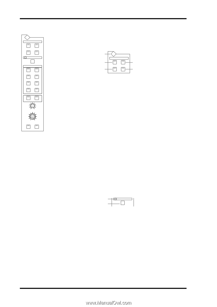
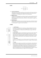
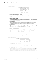
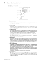
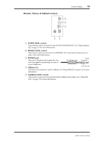
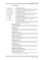
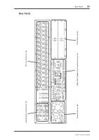
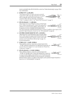
20 Chapter 2-Control Surface & Rear Panel MONITOR Section MONITOR DISPLAY STUDIO CONTROL STEREO ROOM AUX7 AUX8 SOLO CLEAR CONTROL ROOM 2TR D1 2TR A1 The various subsections of the MONITOR section are explained below. STUDIO 1 2 4 MONITOR DISPLAY STUDIO CONTROL STEREO ROOM AUX7 AUX8 3 5 2TR D2 2TR A2 2TR D3 STEREO ASSIGN1 ASSIGN2 SURROUND BUS SLOT 0 10 SURROUND MONITOR LEVEL 0 10 CONTROL ROOM LEVEL DIMMER TALKBACK A MONITOR DISPLAY button This button is used to select the following pages: Solo Setting, Control Room Setup, and Talkback Setup. See "Configuring Solo" on page 102, "Control Room Monitoring" on page 114, and "Using Talkback" on page 121 respectively for more information. When a Surround Pan mode is selected, the following pages can also be selected: Surround Monitor, Surround Monitor Setup, Surround Monitor Patch, and Surround Monitor Library. See "Surround Monitoring" on page 116 for more information. B CONTROL ROOM button This button selects the Control Room Monitor signal as the Studio Monitor signal source. Its indicator lights up when this source is selected. See "Studio Monitoring" on page 115 for more information. C STEREO button This button selects the Stereo Out signal as the Studio Monitor signal source. Its indicator lights up when this source is selected. See "Studio Monitoring" on page 115 for more information. D AUX 7 button This button selects Aux Send #7 as the Studio Monitor signal source. Its indicator lights up when this source is selected. See "Studio Monitoring" on page 115 for more information. E AUX 8 button This button selects Aux Send #8 as the Studio Monitor signal source. Its indicator lights up when this source is selected. See "Studio Monitoring" on page 115 for more information. SOLO 1 2 SOLO CLEAR A SOLO indicator This indicator flashes when one or more Channels are soloed, indicating that the Solo function is active. See "Soloing Channels" on page 102 for more information. B CLEAR button This button can be used to unsolo all soloed Channels. See "Soloing Channels" on page 102 for more information. 02R96-Owner's Manual
-
 1
1 -
2
-
3
-
4
-
5
-
6
-
7
-
8
-
9
-
10
-
11
-
12
-
13
-
14
-
15
-
16
-
17
-
18
-
19
-
20
-
21
-
22
-
23
-
24
-
25
-
26
-
27
-
 28
28 -
 29
29 -
 30
30 -
 31
31 -
 32
32 -
 33
33 -
 34
34 -
 35
35 -
 36
36 -
 37
37 -
 38
38 -
39
-
40
-
41
-
42
-
43
-
44
-
45
-
46
-
47
-
48
-
49
-
50
-
51
-
52
-
53
-
54
-
55
-
56
-
57
-
58
-
59
-
60
-
61
-
62
-
63
-
64
-
65
-
66
-
67
-
68
-
69
-
70
-
71
-
72
-
73
-
74
-
75
-
76
-
77
-
78
-
79
-
80
-
81
-
82
-
83
-
84
-
85
-
86
-
87
-
88
-
89
-
90
-
91
-
92
-
93
-
94
-
95
-
96
-
97
-
98
-
99
-
100
-
101
-
102
-
103
-
104
-
105
-
106
-
107
-
108
-
109
-
110
-
111
-
112
-
113
-
114
-
115
-
116
-
117
-
118
-
119
-
120
-
121
-
122
-
123
-
124
-
125
-
126
-
127
-
128
-
129
-
130
-
131
-
132
-
133
-
134
-
135
-
136
-
137
-
138
-
139
-
140
-
141
-
142
-
143
-
144
-
145
-
146
-
147
-
148
-
149
-
150
-
151
-
152
-
153
-
154
-
155
-
156
-
157
-
158
-
159
-
160
-
161
-
162
-
163
-
164
-
165
-
166
-
167
-
168
-
169
-
170
-
171
-
172
-
173
-
174
-
175
-
176
-
177
-
178
-
179
-
180
-
181
-
182
-
183
-
184
-
185
-
186
-
187
-
188
-
189
-
190
-
191
-
192
-
193
-
194
-
195
-
196
-
197
-
198
-
199
-
200
-
201
-
202
-
203
-
204
-
205
-
206
-
207
-
208
-
209
-
210
-
211
-
212
-
213
-
214
-
215
-
216
-
217
-
218
-
219
-
220
-
221
-
222
-
223
-
224
-
225
-
226
-
227
-
228
-
229
-
230
-
231
-
232
-
233
-
234
-
235
-
236
-
237
-
238
-
239
-
240
-
241
-
242
-
243
-
244
-
245
-
246
-
247
-
248
-
249
-
250
-
251
-
252
-
253
-
254
-
255
-
256
-
257
-
258
-
259
-
260
-
261
-
262
-
263
-
264
-
265
-
266
-
267
-
268
-
269
-
270
-
271
-
272
-
273
-
274
-
275
-
276
-
277
-
278
-
279
-
280
-
281
-
282
-
283
-
284
-
285
-
286
-
287
-
288
-
289
-
290
-
291
-
292
-
293
-
294
-
295
-
296
-
297
-
298
-
299
-
300
-
301
-
302
-
303
-
304
-
305
-
306
-
307
-
308
-
309
-
310
-
311
-
312
-
313
-
314
-
315
 |
 |