Yamaha 02R96 Owner's Manual - Page 18
AD Input Channel strips, INSERT ON/OFF switches AD 1-16 - phantom power
 |
View all Yamaha 02R96 manuals
Add to My Manuals
Save this manual to your list of manuals |
Page 18 highlights
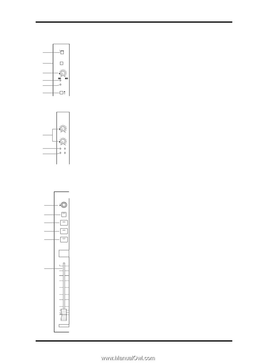
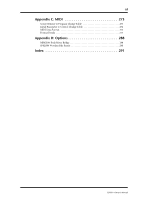
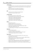
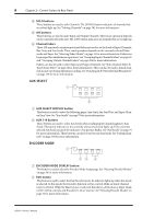
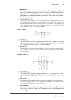
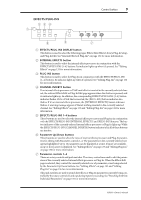
Control Surface 5 AD Input Section AD Input #1 is shown at the top; AD Inputs #17 and #18 below. 1 2 3 4 5 6 +48V ON OFF PAD 26dB -16 -60 GAIN PEAK SIGNAL 1 OFF ON INSERT A +48V ON/OFF switches (AD 1-16) These switches turn on and off the +48 V phantom power feed to each INPUT A (XLR-type connector). Phantom power is typically used to power condenser-type microphones or direct boxes. See "Phantom Power (AD 1-16)" on page 39 for more information. B PAD switches (AD 1-16) These switches turn on and off the 26 dB pad (attenuator) for each AD Input. See "Pad (AD 1-16)" on page 39 for more information. C GAIN controls These controls adjust the gain of the AD Input Head Amps. They have an input sensitivity of -16 dB to -60 dB or +10 dB to -34 dB when Pad is on. AD Inputs 17 to 24 have an input sensitivity of +10 dB to -34 dB. See "Gain" on page 39 for more information. 17 D PEAK indicators These indicators light up when the input signal level is 3 dB below clipping. See "PEAK 3 +10 34 GAIN & SIGNAL Indicators" on page 39 for more information. 18 E SIGNAL indicators +10 34 4 GAIN These indicators light up when the input signal level is 20 dB below nominal. See PEAK 5 SIGNAL "PEAK & SIGNAL Indicators" on page 39 for more information. 17 18 F INSERT ON/OFF switches (AD 1-16) These switches are for turning on and off the AD Input inserts. See "AD Inserts (AD 1-16)" on page 40 for more information. Channel strips Channel strip #1 is shown here. The function of each channel strip depends on the currently selected Layer. See 1 "Selecting Layers" on page 33 for more information. 2 A Encoders AUTO These controls are used to edit Input and Output Channel parameters. Their exact 3 operation depends on the currently selected Encoder mode and Layer. There are two 4 SEL SOLO preset Encoder modes, Pan and Aux, and two assignable modes, with over 40 parameters to choose from. See "Selecting Encoder Modes" on page 36 for more informa- 5 tion. ON The Encoders feature push switches that are used to punch the parameter currently 1 assigned to the Encoders in and out during Automix recording. See "Punching In & Out Individual Parameters" on page 156 for more information. 10 6 5 0 5 10 B AUTO buttons These buttons are used to set Automix recording and playback for each channel. Their exact operation depends on the currently selected Layer. Their indicators light up orange in Record-Ready mode, red while recording, and green during playback. See "Channel Strip [AUTO] Buttons" on page 149 for more information. 15 C SEL buttons 20 These buttons are used to select Input and Output Channels for editing with the 30 SELECTED CHANNEL section. Their exact operation depends on the currently 40 50 selected Layer. The [SEL] button indicator of the currently selected channel lights up. See "Selecting Channels" on page 34 for more information. The [SEL] buttons can also be used to pair channels, and to add and remove channels to and from the EQ, 1 25 Comp, Fader, and Mute groups. 49 02R96-Owner's Manual
-
 1
1 -
2
-
3
-
4
-
5
-
6
-
7
-
8
-
9
-
10
-
11
-
12
-
 13
13 -
 14
14 -
 15
15 -
 16
16 -
 17
17 -
 18
18 -
 19
19 -
 20
20 -
 21
21 -
 22
22 -
 23
23 -
24
-
25
-
26
-
27
-
28
-
29
-
30
-
31
-
32
-
33
-
34
-
35
-
36
-
37
-
38
-
39
-
40
-
41
-
42
-
43
-
44
-
45
-
46
-
47
-
48
-
49
-
50
-
51
-
52
-
53
-
54
-
55
-
56
-
57
-
58
-
59
-
60
-
61
-
62
-
63
-
64
-
65
-
66
-
67
-
68
-
69
-
70
-
71
-
72
-
73
-
74
-
75
-
76
-
77
-
78
-
79
-
80
-
81
-
82
-
83
-
84
-
85
-
86
-
87
-
88
-
89
-
90
-
91
-
92
-
93
-
94
-
95
-
96
-
97
-
98
-
99
-
100
-
101
-
102
-
103
-
104
-
105
-
106
-
107
-
108
-
109
-
110
-
111
-
112
-
113
-
114
-
115
-
116
-
117
-
118
-
119
-
120
-
121
-
122
-
123
-
124
-
125
-
126
-
127
-
128
-
129
-
130
-
131
-
132
-
133
-
134
-
135
-
136
-
137
-
138
-
139
-
140
-
141
-
142
-
143
-
144
-
145
-
146
-
147
-
148
-
149
-
150
-
151
-
152
-
153
-
154
-
155
-
156
-
157
-
158
-
159
-
160
-
161
-
162
-
163
-
164
-
165
-
166
-
167
-
168
-
169
-
170
-
171
-
172
-
173
-
174
-
175
-
176
-
177
-
178
-
179
-
180
-
181
-
182
-
183
-
184
-
185
-
186
-
187
-
188
-
189
-
190
-
191
-
192
-
193
-
194
-
195
-
196
-
197
-
198
-
199
-
200
-
201
-
202
-
203
-
204
-
205
-
206
-
207
-
208
-
209
-
210
-
211
-
212
-
213
-
214
-
215
-
216
-
217
-
218
-
219
-
220
-
221
-
222
-
223
-
224
-
225
-
226
-
227
-
228
-
229
-
230
-
231
-
232
-
233
-
234
-
235
-
236
-
237
-
238
-
239
-
240
-
241
-
242
-
243
-
244
-
245
-
246
-
247
-
248
-
249
-
250
-
251
-
252
-
253
-
254
-
255
-
256
-
257
-
258
-
259
-
260
-
261
-
262
-
263
-
264
-
265
-
266
-
267
-
268
-
269
-
270
-
271
-
272
-
273
-
274
-
275
-
276
-
277
-
278
-
279
-
280
-
281
-
282
-
283
-
284
-
285
-
286
-
287
-
288
-
289
-
290
-
291
-
292
-
293
-
294
-
295
-
296
-
297
-
298
-
299
-
300
-
301
-
302
-
303
-
304
-
305
-
306
-
307
-
308
-
309
-
310
-
311
-
312
-
313
-
314
-
315
 |
 |