Yamaha 02R96 Owner's Manual - Page 128
Studio Monitoring, Control Room Setup
 |
View all Yamaha 02R96 manuals
Add to My Manuals
Save this manual to your list of manuals |
Page 128 highlights
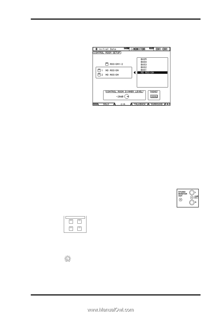
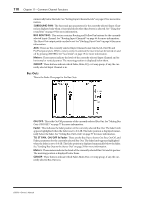
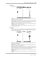
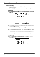
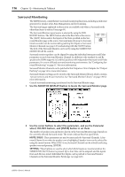
Studio Monitoring 115 Control Room Setup Control room monitoring is configured on the Control Room Setup page. 1 Use the MONITOR [DISPLAY] button to locate the Control Room Setup page. 2 Use the cursor buttons to select the ASSIGN buttons in the left-hand box, and use the Parameter wheel to select an Output Channel in the right-hand box. Bus Outs or Aux Sends can be assigned to the [ASSIGN 1] and [ASSIGN 2] buttons. 3 Press [ENTER] to assign the selected Output Channel. Once assigned, the selected Output Channel appears highlighted in the right-hand box. The other parameters on this page are as follows. CONTROL ROOM DIMMER LEVEL: This determines the amount of attenuation applied to the Control Room Monitor and Surround Monitor signals by the Dimmer function. Use the cursor buttons to select it, and use the Parameter wheel or INC/DEC buttons to set it from. MONO: This button is be used to switch the Control Room Monitor signal into mono. Studio Monitoring The STUDIO MONITOR OUT uses balanced 1/4-inch phone jacks, nominal level +4 dB. Typically it's used to feed monitoring systems in the actual studio. STUDIO CONTROL STEREO ROOM AUX7 AUX8 The Studio Monitor signal source is selected by using the STUDIO buttons. [CONTROL ROOM]: Selects the Control Room Monitor. [STEREO]: Selects the Stereo Out. [AUX 7]: Selects Aux Send #7. [AUX 8]: Selects Aux Send #8. The level of the Studio Monitor signal can be set by using the STUDIO LEVEL 0 10 STUDIO LEVEL control. 02R96-Owner's Manual
-
 1
1 -
2
-
3
-
4
-
5
-
6
-
7
-
8
-
9
-
10
-
11
-
12
-
13
-
14
-
15
-
16
-
17
-
18
-
19
-
20
-
21
-
22
-
23
-
24
-
25
-
26
-
27
-
28
-
29
-
30
-
31
-
32
-
33
-
34
-
35
-
36
-
37
-
38
-
39
-
40
-
41
-
42
-
43
-
44
-
45
-
46
-
47
-
48
-
49
-
50
-
51
-
52
-
53
-
54
-
55
-
56
-
57
-
58
-
59
-
60
-
61
-
62
-
63
-
64
-
65
-
66
-
67
-
68
-
69
-
70
-
71
-
72
-
73
-
74
-
75
-
76
-
77
-
78
-
79
-
80
-
81
-
82
-
83
-
84
-
85
-
86
-
87
-
88
-
89
-
90
-
91
-
92
-
93
-
94
-
95
-
96
-
97
-
98
-
99
-
100
-
101
-
102
-
103
-
104
-
105
-
106
-
107
-
108
-
109
-
110
-
111
-
112
-
113
-
114
-
115
-
116
-
117
-
118
-
119
-
120
-
121
-
122
-
 123
123 -
 124
124 -
 125
125 -
 126
126 -
 127
127 -
 128
128 -
 129
129 -
 130
130 -
 131
131 -
 132
132 -
 133
133 -
134
-
135
-
136
-
137
-
138
-
139
-
140
-
141
-
142
-
143
-
144
-
145
-
146
-
147
-
148
-
149
-
150
-
151
-
152
-
153
-
154
-
155
-
156
-
157
-
158
-
159
-
160
-
161
-
162
-
163
-
164
-
165
-
166
-
167
-
168
-
169
-
170
-
171
-
172
-
173
-
174
-
175
-
176
-
177
-
178
-
179
-
180
-
181
-
182
-
183
-
184
-
185
-
186
-
187
-
188
-
189
-
190
-
191
-
192
-
193
-
194
-
195
-
196
-
197
-
198
-
199
-
200
-
201
-
202
-
203
-
204
-
205
-
206
-
207
-
208
-
209
-
210
-
211
-
212
-
213
-
214
-
215
-
216
-
217
-
218
-
219
-
220
-
221
-
222
-
223
-
224
-
225
-
226
-
227
-
228
-
229
-
230
-
231
-
232
-
233
-
234
-
235
-
236
-
237
-
238
-
239
-
240
-
241
-
242
-
243
-
244
-
245
-
246
-
247
-
248
-
249
-
250
-
251
-
252
-
253
-
254
-
255
-
256
-
257
-
258
-
259
-
260
-
261
-
262
-
263
-
264
-
265
-
266
-
267
-
268
-
269
-
270
-
271
-
272
-
273
-
274
-
275
-
276
-
277
-
278
-
279
-
280
-
281
-
282
-
283
-
284
-
285
-
286
-
287
-
288
-
289
-
290
-
291
-
292
-
293
-
294
-
295
-
296
-
297
-
298
-
299
-
300
-
301
-
302
-
303
-
304
-
305
-
306
-
307
-
308
-
309
-
310
-
311
-
312
-
313
-
314
-
315
 |
 |