Yamaha 02R96 Owner's Manual - Page 263
Compand 5.1
 |
View all Yamaha 02R96 manuals
Add to My Manuals
Save this manual to your list of manuals |
Page 263 highlights
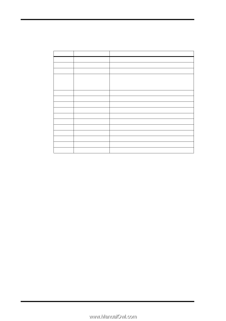
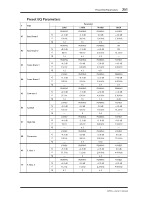
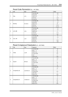
250 Appendix A: Parameter Lists COMPAND 5.1 Six input, six output compander for 5.1 surround, with individual solo for each band, and gain reduction metering of left and right (L+R), left surround and right surround (LS+RS), center (C), or LFE channels. Parameter Range Description LOW GAIN MID GAIN HI. GAIN -96.0 to +12.0 dB -96.0 to +12.0 dB -96.0 to +12.0 dB PRESENCE -10 to +10 THRE RATIO ATTACK WIDTH TYPE LOOKUP CEILING L-M XOVR M-H XOVR SLOPE KEY LINK -24.0 dB to 0.0 dB 1:1 to 20:1 0-120 ms 1-90 dB Soft, Hard 0.0-100.0 ms -6.0 dB to 0.0 dB, OFF 21.2 Hz-8.00 kHz 21.2 Hz-8.00 kHz -6 dB to -12 dB 1 Low band level Mid band level High band level For positive values, the threshold of the high band is lowered and the threshold of the low band is increased. For negative values, the opposite will occur. When set to 0, all three bands are affected the same. Compressor threshold Compressor ratio Compressor attack Width before the expander operates Compander type Lookup delay Specifies the maximum output level Low/mid crossover frequency Mid/high crossover frequency Filter slope Key-in linking 1. 5.1: key-in of all inputs are linked. 5.0: key-in of the L, C, R, LS, and RS are linked (LFE is independent). 3+2: key-in of L, C, and R are linked, and LS and RS are linked. 2+2: key-in of L and R are linked, and LS and RS are linked. 02R96-Owner's Manual
-
 1
1 -
2
-
3
-
4
-
5
-
6
-
7
-
8
-
9
-
10
-
11
-
12
-
13
-
14
-
15
-
16
-
17
-
18
-
19
-
20
-
21
-
22
-
23
-
24
-
25
-
26
-
27
-
28
-
29
-
30
-
31
-
32
-
33
-
34
-
35
-
36
-
37
-
38
-
39
-
40
-
41
-
42
-
43
-
44
-
45
-
46
-
47
-
48
-
49
-
50
-
51
-
52
-
53
-
54
-
55
-
56
-
57
-
58
-
59
-
60
-
61
-
62
-
63
-
64
-
65
-
66
-
67
-
68
-
69
-
70
-
71
-
72
-
73
-
74
-
75
-
76
-
77
-
78
-
79
-
80
-
81
-
82
-
83
-
84
-
85
-
86
-
87
-
88
-
89
-
90
-
91
-
92
-
93
-
94
-
95
-
96
-
97
-
98
-
99
-
100
-
101
-
102
-
103
-
104
-
105
-
106
-
107
-
108
-
109
-
110
-
111
-
112
-
113
-
114
-
115
-
116
-
117
-
118
-
119
-
120
-
121
-
122
-
123
-
124
-
125
-
126
-
127
-
128
-
129
-
130
-
131
-
132
-
133
-
134
-
135
-
136
-
137
-
138
-
139
-
140
-
141
-
142
-
143
-
144
-
145
-
146
-
147
-
148
-
149
-
150
-
151
-
152
-
153
-
154
-
155
-
156
-
157
-
158
-
159
-
160
-
161
-
162
-
163
-
164
-
165
-
166
-
167
-
168
-
169
-
170
-
171
-
172
-
173
-
174
-
175
-
176
-
177
-
178
-
179
-
180
-
181
-
182
-
183
-
184
-
185
-
186
-
187
-
188
-
189
-
190
-
191
-
192
-
193
-
194
-
195
-
196
-
197
-
198
-
199
-
200
-
201
-
202
-
203
-
204
-
205
-
206
-
207
-
208
-
209
-
210
-
211
-
212
-
213
-
214
-
215
-
216
-
217
-
218
-
219
-
220
-
221
-
222
-
223
-
224
-
225
-
226
-
227
-
228
-
229
-
230
-
231
-
232
-
233
-
234
-
235
-
236
-
237
-
238
-
239
-
240
-
241
-
242
-
243
-
244
-
245
-
246
-
247
-
248
-
249
-
250
-
251
-
252
-
253
-
254
-
255
-
256
-
257
-
 258
258 -
 259
259 -
 260
260 -
 261
261 -
 262
262 -
 263
263 -
 264
264 -
 265
265 -
 266
266 -
 267
267 -
 268
268 -
269
-
270
-
271
-
272
-
273
-
274
-
275
-
276
-
277
-
278
-
279
-
280
-
281
-
282
-
283
-
284
-
285
-
286
-
287
-
288
-
289
-
290
-
291
-
292
-
293
-
294
-
295
-
296
-
297
-
298
-
299
-
300
-
301
-
302
-
303
-
304
-
305
-
306
-
307
-
308
-
309
-
310
-
311
-
312
-
313
-
314
-
315
 |
 |