Yamaha 02R96 Owner's Manual - Page 261
M. BAND DYNA., Two input, two output 3-band dynamics processor
 |
View all Yamaha 02R96 manuals
Add to My Manuals
Save this manual to your list of manuals |
Page 261 highlights
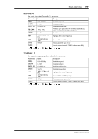
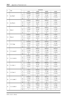
248 Appendix A: Parameter Lists M. BAND DYNA. Two input, two output 3-band dynamics processor, with individual solo and gain reduction metering for each band. Parameter Range Description LOW GAIN MID GAIN HI. GAIN -96.0 to +12.0 dB -96.0 to +12.0 dB -96.0 to +12.0 dB PRESENCE -10 to +10 EXP. THRE EXP. RAT EXP. REL EXP. BYP CMP. THRE CMP. RAT CMP. REL CMP. ATK CMP. KNEE CMP. BYP LIM. THRE LIM. REL LIM. ATK LIM. KNEE LIM. BYP LOOKUP L-M XOVR M-H XOVR SLOPE CEILING -54.0 dB to -24.0 dB 1:1 to ∞:1 1 ON/OFF -24.0 dB to 0.0 dB 1:1 to 20:1 1 0-120 ms 0-5 ON/OFF -12.0 dB to 0.0 dB 1 0-120 ms 0-5 ON/OFF 0.0-100.0 ms 21.2 Hz-8.00 kHz 21.2 Hz-8.00 kHz -6 dB to -12 dB -6.0 dB to 0.0 dB, OFF Low band level Mid band level High band level For positive values, the threshold of the high band is lowered and the threshold of the low band is increased. For negative values, the opposite will occur. When set to 0, all three bands are affected the same. Expander threshold Expander ratio Expander release time Expander bypass Compressor threshold Compressor ratio Compressor release time Compressor attack Compressor knee Compressor bypass Limiter threshold Limiter release time Limiter attack Limiter knee Limiter bypass Lookup delay Low/mid crossover frequency Mid/high crossover frequency Filter slope Specifies the maximum output level 1. 6.0 ms-46.0 s (fs=44.1 kHz), 5.0 ms-42.3 s (fs=48 kHz), 3 ms-23.0 s (fs=88.2 kHz), 3 ms-21.1 s (fs=96 kHz) 02R96-Owner's Manual
-
 1
1 -
2
-
3
-
4
-
5
-
6
-
7
-
8
-
9
-
10
-
11
-
12
-
13
-
14
-
15
-
16
-
17
-
18
-
19
-
20
-
21
-
22
-
23
-
24
-
25
-
26
-
27
-
28
-
29
-
30
-
31
-
32
-
33
-
34
-
35
-
36
-
37
-
38
-
39
-
40
-
41
-
42
-
43
-
44
-
45
-
46
-
47
-
48
-
49
-
50
-
51
-
52
-
53
-
54
-
55
-
56
-
57
-
58
-
59
-
60
-
61
-
62
-
63
-
64
-
65
-
66
-
67
-
68
-
69
-
70
-
71
-
72
-
73
-
74
-
75
-
76
-
77
-
78
-
79
-
80
-
81
-
82
-
83
-
84
-
85
-
86
-
87
-
88
-
89
-
90
-
91
-
92
-
93
-
94
-
95
-
96
-
97
-
98
-
99
-
100
-
101
-
102
-
103
-
104
-
105
-
106
-
107
-
108
-
109
-
110
-
111
-
112
-
113
-
114
-
115
-
116
-
117
-
118
-
119
-
120
-
121
-
122
-
123
-
124
-
125
-
126
-
127
-
128
-
129
-
130
-
131
-
132
-
133
-
134
-
135
-
136
-
137
-
138
-
139
-
140
-
141
-
142
-
143
-
144
-
145
-
146
-
147
-
148
-
149
-
150
-
151
-
152
-
153
-
154
-
155
-
156
-
157
-
158
-
159
-
160
-
161
-
162
-
163
-
164
-
165
-
166
-
167
-
168
-
169
-
170
-
171
-
172
-
173
-
174
-
175
-
176
-
177
-
178
-
179
-
180
-
181
-
182
-
183
-
184
-
185
-
186
-
187
-
188
-
189
-
190
-
191
-
192
-
193
-
194
-
195
-
196
-
197
-
198
-
199
-
200
-
201
-
202
-
203
-
204
-
205
-
206
-
207
-
208
-
209
-
210
-
211
-
212
-
213
-
214
-
215
-
216
-
217
-
218
-
219
-
220
-
221
-
222
-
223
-
224
-
225
-
226
-
227
-
228
-
229
-
230
-
231
-
232
-
233
-
234
-
235
-
236
-
237
-
238
-
239
-
240
-
241
-
242
-
243
-
244
-
245
-
246
-
247
-
248
-
249
-
250
-
251
-
252
-
253
-
254
-
255
-
 256
256 -
 257
257 -
 258
258 -
 259
259 -
 260
260 -
 261
261 -
 262
262 -
 263
263 -
 264
264 -
 265
265 -
 266
266 -
267
-
268
-
269
-
270
-
271
-
272
-
273
-
274
-
275
-
276
-
277
-
278
-
279
-
280
-
281
-
282
-
283
-
284
-
285
-
286
-
287
-
288
-
289
-
290
-
291
-
292
-
293
-
294
-
295
-
296
-
297
-
298
-
299
-
300
-
301
-
302
-
303
-
304
-
305
-
306
-
307
-
308
-
309
-
310
-
311
-
312
-
313
-
314
-
315
 |
 |
