Yamaha 02R96 Owner's Manual - Page 20
CAUX button DASSIGN 1 & 2 buttons AFADER button BAUX button AAUTOMIX button BDIO button CSETUP button
 |
View all Yamaha 02R96 manuals
Add to My Manuals
Save this manual to your list of manuals |
Page 20 highlights
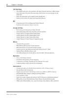
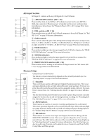
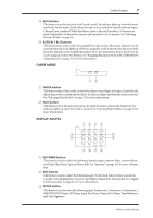
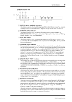
Control Surface 7 C AUX button This button is used to select the Aux Encoder mode. Its indicator lights up when this mode is selected. In this mode, the Encoders function as Aux Send level controls when an Input Channel Layer is selected. While the Master Layer is selected, Encoders 1-8 function as Input Channel 49-56 Aux Send controls, and Encoders 9-24 are inactive. See "Selecting Encoder Modes" on page 36. D ASSIGN 1 & 2 buttons These buttons are used to select the assignable Encoder modes. The button indicator for the currently selected mode lights up. When an assignable mode is selected, the function of the Encoders depends on the assigned parameter. Up to two parameters, from a list of over 40, can be assigned to these two buttons. See "Assigning Parameters to the ENCODER MODE Assign Buttons" on page 37 for more information. FADER MODE FADER MODE FADER AUX 12 A FADER button This button selects Fader mode, in which the faders control Input or Output Channel levels, depending on the currently selected Layer. Its indicator lights up when this mode is selected. See "Selecting Fader Modes" on page 35 for more information. B AUX button This button selects the Aux Fader mode, in which the faders control Aux Send levels. Its indicator lights up when this mode is selected. See "Selecting Fader Modes" on page 35 for more information. DISPLAY ACCESS 1234 DISPLAY ACCESS 5 6 AUTOMIX DIO SETUP UTILITY MIDI REMOTE METER VIEW 7 8 PAIR GROUP INPUT PATCH OUTPUT PATCH 9JKL A AUTOMIX button This button is used to select the following Automix pages: Automix Main, Automix Memory, Fader Edit, Event Copy, and Event Edit. See "Automix" on page 145 for more information. B DIO button This button is used to select the following pages: Word Clock Select, Dither, Cascade In, Cascade Out, Sampling Rate Converter, and Higher Sample Rate Data Format. See "Digital I/O & Cascading" on page 41 for more information. C SETUP button This button is used to select the following pages: Preferences 1, Preferences 2, Preferences 3, MIDI/TO HOST Setup, GPI Setup, Input Port Name, Output Port Name, Time Reference, and Time Signature. 02R96-Owner's Manual
-
 1
1 -
2
-
3
-
4
-
5
-
6
-
7
-
8
-
9
-
10
-
11
-
12
-
13
-
14
-
 15
15 -
 16
16 -
 17
17 -
 18
18 -
 19
19 -
 20
20 -
 21
21 -
 22
22 -
 23
23 -
 24
24 -
 25
25 -
26
-
27
-
28
-
29
-
30
-
31
-
32
-
33
-
34
-
35
-
36
-
37
-
38
-
39
-
40
-
41
-
42
-
43
-
44
-
45
-
46
-
47
-
48
-
49
-
50
-
51
-
52
-
53
-
54
-
55
-
56
-
57
-
58
-
59
-
60
-
61
-
62
-
63
-
64
-
65
-
66
-
67
-
68
-
69
-
70
-
71
-
72
-
73
-
74
-
75
-
76
-
77
-
78
-
79
-
80
-
81
-
82
-
83
-
84
-
85
-
86
-
87
-
88
-
89
-
90
-
91
-
92
-
93
-
94
-
95
-
96
-
97
-
98
-
99
-
100
-
101
-
102
-
103
-
104
-
105
-
106
-
107
-
108
-
109
-
110
-
111
-
112
-
113
-
114
-
115
-
116
-
117
-
118
-
119
-
120
-
121
-
122
-
123
-
124
-
125
-
126
-
127
-
128
-
129
-
130
-
131
-
132
-
133
-
134
-
135
-
136
-
137
-
138
-
139
-
140
-
141
-
142
-
143
-
144
-
145
-
146
-
147
-
148
-
149
-
150
-
151
-
152
-
153
-
154
-
155
-
156
-
157
-
158
-
159
-
160
-
161
-
162
-
163
-
164
-
165
-
166
-
167
-
168
-
169
-
170
-
171
-
172
-
173
-
174
-
175
-
176
-
177
-
178
-
179
-
180
-
181
-
182
-
183
-
184
-
185
-
186
-
187
-
188
-
189
-
190
-
191
-
192
-
193
-
194
-
195
-
196
-
197
-
198
-
199
-
200
-
201
-
202
-
203
-
204
-
205
-
206
-
207
-
208
-
209
-
210
-
211
-
212
-
213
-
214
-
215
-
216
-
217
-
218
-
219
-
220
-
221
-
222
-
223
-
224
-
225
-
226
-
227
-
228
-
229
-
230
-
231
-
232
-
233
-
234
-
235
-
236
-
237
-
238
-
239
-
240
-
241
-
242
-
243
-
244
-
245
-
246
-
247
-
248
-
249
-
250
-
251
-
252
-
253
-
254
-
255
-
256
-
257
-
258
-
259
-
260
-
261
-
262
-
263
-
264
-
265
-
266
-
267
-
268
-
269
-
270
-
271
-
272
-
273
-
274
-
275
-
276
-
277
-
278
-
279
-
280
-
281
-
282
-
283
-
284
-
285
-
286
-
287
-
288
-
289
-
290
-
291
-
292
-
293
-
294
-
295
-
296
-
297
-
298
-
299
-
300
-
301
-
302
-
303
-
304
-
305
-
306
-
307
-
308
-
309
-
310
-
311
-
312
-
313
-
314
-
315
 |
 |