Yamaha 02R96 Owner's Manual - Page 40
Midi In, Out & Thru Ports, 2tr In Digital Coaxial 2 & 3
 |
View all Yamaha 02R96 manuals
Add to My Manuals
Save this manual to your list of manuals |
Page 40 highlights
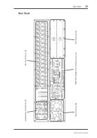
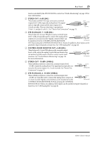
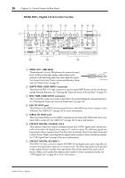
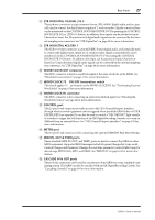
Rear Panel 27 H 2TR IN DIGITAL COAXIAL 2 & 3 These phono connectors accept consumer format (IEC-60958) digital audio, and are typically used to connect the digital stereo outputs of 2-track recorders. Signals connected here can be monitored via the CONTROL ROOM MONITOR OUT by pressing the CONTROL ROOM [2TR D2] or [2TR D3] button. In addition, these inputs can be patched to Input Channels or Insert Ins. Unsynchronized digital audio signals can be converted by the internal sampling rate converters. See "2TR Digital Ins" on page 44 for more information. I 2TR IN DIGITAL AES/EBU 1 This XLR-3-31-type connector accepts AES/EBU format digital audio, and is typically used to connect the digital stereo output of a 2-track recorder. Signals connected here can be monitored via the CONTROL ROOM MONITOR OUT by pressing the CONTROL ROOM [2TR D1] button. In addition, this input can be patched to Input Channels or Insert Ins. Unsynchronized digital audio signals can be converted by the internal sampling rate converters. See "2TR Digital Ins" on page 44 for more information. J WORD CLOCK OUT connector This BNC connector outputs a wordclock signal at the same clock rate as the 02R96. See "Wordclock Connections" on page 41 for more information. K WORD CLOCK 75Ω ON/OFF termination switch This switch applies 75Ω termination to the WORD CLOCK IN. See "Terminating External Wordclocks" on page 43 for more information. L WORD CLOCK IN connector This BNC connector is for connecting an external wordclock signal. See "Selecting the Wordclock Source" on page 42 for more information. M CONTROL port This 25-pin D-sub connector provides access to the GPI (General Purpose Interface) through which external equipment can be triggered when specified 02R96 faders or USER DEFINE KEYS are operated. It can also be used to control a "RECORDING" light outside of a studio, to trigger the Solo function of an 02R Digital Recording Console, or to turn on Talkback from an external device. See "GPI (General Purpose Interface)" on page 195 for more information. N METER port This 15-pin D-sub connector is for connecting the optional MB02R96 Peak Meter Bridge. O MIDI IN, OUT & THRU ports These standard MIDI IN, OUT, and THRU ports are used to connect the 02R96 to other MIDI equipment. Supported MIDI messages include Program Changes for Scene recall, Control Changes and Parameter Changes for real-time parameter control, Bulk Dump for data storage, MIDI Clock, MTC, and MMC. See "MIDI I/O" on page 163 for more information. P CASCADE IN & OUT ports These 64-pin connectors can be used to cascade up to four 02R96s to create a multiple-unit mixing system. The 02R96 can also be cascaded with an 02R Digital Recording Console. See "Cascading Consoles" on page 49 for more information. 02R96-Owner's Manual
-
 1
1 -
2
-
3
-
4
-
5
-
6
-
7
-
8
-
9
-
10
-
11
-
12
-
13
-
14
-
15
-
16
-
17
-
18
-
19
-
20
-
21
-
22
-
23
-
24
-
25
-
26
-
27
-
28
-
29
-
30
-
31
-
32
-
33
-
34
-
 35
35 -
 36
36 -
 37
37 -
 38
38 -
 39
39 -
 40
40 -
 41
41 -
 42
42 -
 43
43 -
 44
44 -
 45
45 -
46
-
47
-
48
-
49
-
50
-
51
-
52
-
53
-
54
-
55
-
56
-
57
-
58
-
59
-
60
-
61
-
62
-
63
-
64
-
65
-
66
-
67
-
68
-
69
-
70
-
71
-
72
-
73
-
74
-
75
-
76
-
77
-
78
-
79
-
80
-
81
-
82
-
83
-
84
-
85
-
86
-
87
-
88
-
89
-
90
-
91
-
92
-
93
-
94
-
95
-
96
-
97
-
98
-
99
-
100
-
101
-
102
-
103
-
104
-
105
-
106
-
107
-
108
-
109
-
110
-
111
-
112
-
113
-
114
-
115
-
116
-
117
-
118
-
119
-
120
-
121
-
122
-
123
-
124
-
125
-
126
-
127
-
128
-
129
-
130
-
131
-
132
-
133
-
134
-
135
-
136
-
137
-
138
-
139
-
140
-
141
-
142
-
143
-
144
-
145
-
146
-
147
-
148
-
149
-
150
-
151
-
152
-
153
-
154
-
155
-
156
-
157
-
158
-
159
-
160
-
161
-
162
-
163
-
164
-
165
-
166
-
167
-
168
-
169
-
170
-
171
-
172
-
173
-
174
-
175
-
176
-
177
-
178
-
179
-
180
-
181
-
182
-
183
-
184
-
185
-
186
-
187
-
188
-
189
-
190
-
191
-
192
-
193
-
194
-
195
-
196
-
197
-
198
-
199
-
200
-
201
-
202
-
203
-
204
-
205
-
206
-
207
-
208
-
209
-
210
-
211
-
212
-
213
-
214
-
215
-
216
-
217
-
218
-
219
-
220
-
221
-
222
-
223
-
224
-
225
-
226
-
227
-
228
-
229
-
230
-
231
-
232
-
233
-
234
-
235
-
236
-
237
-
238
-
239
-
240
-
241
-
242
-
243
-
244
-
245
-
246
-
247
-
248
-
249
-
250
-
251
-
252
-
253
-
254
-
255
-
256
-
257
-
258
-
259
-
260
-
261
-
262
-
263
-
264
-
265
-
266
-
267
-
268
-
269
-
270
-
271
-
272
-
273
-
274
-
275
-
276
-
277
-
278
-
279
-
280
-
281
-
282
-
283
-
284
-
285
-
286
-
287
-
288
-
289
-
290
-
291
-
292
-
293
-
294
-
295
-
296
-
297
-
298
-
299
-
300
-
301
-
302
-
303
-
304
-
305
-
306
-
307
-
308
-
309
-
310
-
311
-
312
-
313
-
314
-
315
 |
 |