Yamaha 02R96 Owner's Manual - Page 302
Meter Bridge Controls, PEAK HOLD button
 |
View all Yamaha 02R96 manuals
Add to My Manuals
Save this manual to your list of manuals |
Page 302 highlights
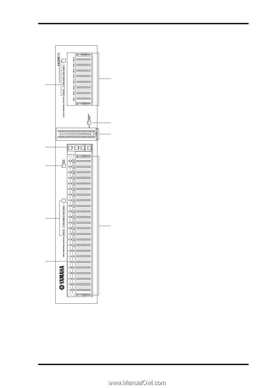
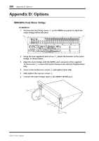
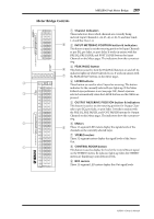
MB02R96 Peak Meter Bridge 289 Meter Bridge Controls A Channel indicators These indicators show which channels are currently being metered: Input Channels 1-24, 25-48, or 49-56 and Aux Sends 1-8 and Bus Outs 1-8. 9 B INPUT METERING POSITION button & indicators 5 This button is used to set the metering position for Input Channels to pre-EQ, pre-fader, or post-fader. It works in unison with the PRE EQ, PRE FADER, and POST FADER buttons for Input Channels on the Meter pages. The indicators show the current set- ting. C PEAK HOLD button 8 This button is used to turn the Peak Hold function on and off. Its indicator lights up when Peak Hold is on. It works in unison with 7 the PEAK HOLD buttons on the Meter pages. OVER 56 4 D LAYER buttons These button are used to select Layers for metering. The button indicator for the currently selected Layer lights up. If the Meter Follow Layer preference is on (see page 198), these Layers are 3 selected automatically when the LAYER buttons on the 02R96 are pressed. E OUTPUT METERING POSITION button & indicators This button is used to set the metering position for Output Channels to pre-EQ, pre-fader, or post-fader. It works in unison with the PRE EQ, PRE FADER, and POST FADER buttons for Output Channels on the Meter pages. The indicators show the current setting. 2 F Meters 6 These 12-segment LED meters display the signals levels of the channels on the currently selected Layer. G STEREO meters These 32-segment meters display the signal levels of the Stereo Out. 1 H CONTROL ROOM button This button is used to display the level of the Control Room signal on the STEREO meters. Its indicator lights up when the STEREO meters are displaying Control Room levels. I BUS meters These 12-segment LED meters display Bus Out signal levels. 02R96-Owner's Manual
-
 1
1 -
2
-
3
-
4
-
5
-
6
-
7
-
8
-
9
-
10
-
11
-
12
-
13
-
14
-
15
-
16
-
17
-
18
-
19
-
20
-
21
-
22
-
23
-
24
-
25
-
26
-
27
-
28
-
29
-
30
-
31
-
32
-
33
-
34
-
35
-
36
-
37
-
38
-
39
-
40
-
41
-
42
-
43
-
44
-
45
-
46
-
47
-
48
-
49
-
50
-
51
-
52
-
53
-
54
-
55
-
56
-
57
-
58
-
59
-
60
-
61
-
62
-
63
-
64
-
65
-
66
-
67
-
68
-
69
-
70
-
71
-
72
-
73
-
74
-
75
-
76
-
77
-
78
-
79
-
80
-
81
-
82
-
83
-
84
-
85
-
86
-
87
-
88
-
89
-
90
-
91
-
92
-
93
-
94
-
95
-
96
-
97
-
98
-
99
-
100
-
101
-
102
-
103
-
104
-
105
-
106
-
107
-
108
-
109
-
110
-
111
-
112
-
113
-
114
-
115
-
116
-
117
-
118
-
119
-
120
-
121
-
122
-
123
-
124
-
125
-
126
-
127
-
128
-
129
-
130
-
131
-
132
-
133
-
134
-
135
-
136
-
137
-
138
-
139
-
140
-
141
-
142
-
143
-
144
-
145
-
146
-
147
-
148
-
149
-
150
-
151
-
152
-
153
-
154
-
155
-
156
-
157
-
158
-
159
-
160
-
161
-
162
-
163
-
164
-
165
-
166
-
167
-
168
-
169
-
170
-
171
-
172
-
173
-
174
-
175
-
176
-
177
-
178
-
179
-
180
-
181
-
182
-
183
-
184
-
185
-
186
-
187
-
188
-
189
-
190
-
191
-
192
-
193
-
194
-
195
-
196
-
197
-
198
-
199
-
200
-
201
-
202
-
203
-
204
-
205
-
206
-
207
-
208
-
209
-
210
-
211
-
212
-
213
-
214
-
215
-
216
-
217
-
218
-
219
-
220
-
221
-
222
-
223
-
224
-
225
-
226
-
227
-
228
-
229
-
230
-
231
-
232
-
233
-
234
-
235
-
236
-
237
-
238
-
239
-
240
-
241
-
242
-
243
-
244
-
245
-
246
-
247
-
248
-
249
-
250
-
251
-
252
-
253
-
254
-
255
-
256
-
257
-
258
-
259
-
260
-
261
-
262
-
263
-
264
-
265
-
266
-
267
-
268
-
269
-
270
-
271
-
272
-
273
-
274
-
275
-
276
-
277
-
278
-
279
-
280
-
281
-
282
-
283
-
284
-
285
-
286
-
287
-
288
-
289
-
290
-
291
-
292
-
293
-
294
-
295
-
296
-
 297
297 -
 298
298 -
 299
299 -
 300
300 -
 301
301 -
 302
302 -
 303
303 -
 304
304 -
 305
305 -
 306
306 -
 307
307 -
308
-
309
-
310
-
311
-
312
-
313
-
314
-
315
 |
 |