Cisco AIR-LAP1252AG-A-K9 Software Configuration Guide - Page 253
Tracing Packets for Ethernet and Radio Ports
 |
UPC - 882658140716
View all Cisco AIR-LAP1252AG-A-K9 manuals
Add to My Manuals
Save this manual to your list of manuals |
Page 253 highlights
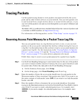
Chapter 9 Diagnostics and Troubleshooting Tracing Packets If you are ready to view packet data, skip to the "Viewing Packet Trace Data" section on page 9-36. If you want to trace all the packets sent through the access point's Ethernet and radio ports, follow the instructions in the "Tracing Packets for Ethernet and Radio Ports" section on page 9-35. Tracing Packets for Ethernet and Radio Ports Follow these steps to set up the access point's Ethernet or radio ports for packet tracing: Step 1 Step 2 Step 3 To trace all the packets sent and received through the access point's Ethernet or radio ports, browse to the Network Ports page. Browse to the Network Ports page by clicking Current Associations on the Summary Status page or by clicking the gray Network button at the top of most management system pages. To trace packets sent or received through the access point's Ethernet port, click Ethernet in the yellow header row. To trace packets sent or received through the access point's radio port, click AP Radio in the yellow header row. The Ethernet Port or AP Radio Port page appears. Click the alert checkbox in the Receive header to trace packets received through the Ethernet or radio port. Click the alert checkbox in the Transmit header to trace packets sent through the Ethernet or Radio port. Note Copying packets into access point memory slows the access point's performance. When you finish tracing packets, deselect the alert checkboxes on the Station pages. If you want the access point to trace packets all the time, reduce the impact on performance by selecting Record for the External Information setting on the Event Handling Setup page and select Port Information on the Event Display Setup page for the "Severity Level at which to display events immediately on the console" setting. With this configuration, the access point records packets in a log file but does not spend time insantly displaying packets on the CLI. Step 4 Click Refresh. The network interface you are tracing appears in red on the Summary Status, Setup, and Network Ports pages. OL-2159-03 Cisco Aironet 1200 Series Access Point Software Configuration Guide 9-35
-
 1
1 -
2
-
3
-
4
-
5
-
6
-
7
-
8
-
9
-
10
-
11
-
12
-
13
-
14
-
15
-
16
-
17
-
18
-
19
-
20
-
21
-
22
-
23
-
24
-
25
-
26
-
27
-
28
-
29
-
30
-
31
-
32
-
33
-
34
-
35
-
36
-
37
-
38
-
39
-
40
-
41
-
42
-
43
-
44
-
45
-
46
-
47
-
48
-
49
-
50
-
51
-
52
-
53
-
54
-
55
-
56
-
57
-
58
-
59
-
60
-
61
-
62
-
63
-
64
-
65
-
66
-
67
-
68
-
69
-
70
-
71
-
72
-
73
-
74
-
75
-
76
-
77
-
78
-
79
-
80
-
81
-
82
-
83
-
84
-
85
-
86
-
87
-
88
-
89
-
90
-
91
-
92
-
93
-
94
-
95
-
96
-
97
-
98
-
99
-
100
-
101
-
102
-
103
-
104
-
105
-
106
-
107
-
108
-
109
-
110
-
111
-
112
-
113
-
114
-
115
-
116
-
117
-
118
-
119
-
120
-
121
-
122
-
123
-
124
-
125
-
126
-
127
-
128
-
129
-
130
-
131
-
132
-
133
-
134
-
135
-
136
-
137
-
138
-
139
-
140
-
141
-
142
-
143
-
144
-
145
-
146
-
147
-
148
-
149
-
150
-
151
-
152
-
153
-
154
-
155
-
156
-
157
-
158
-
159
-
160
-
161
-
162
-
163
-
164
-
165
-
166
-
167
-
168
-
169
-
170
-
171
-
172
-
173
-
174
-
175
-
176
-
177
-
178
-
179
-
180
-
181
-
182
-
183
-
184
-
185
-
186
-
187
-
188
-
189
-
190
-
191
-
192
-
193
-
194
-
195
-
196
-
197
-
198
-
199
-
200
-
201
-
202
-
203
-
204
-
205
-
206
-
207
-
208
-
209
-
210
-
211
-
212
-
213
-
214
-
215
-
216
-
217
-
218
-
219
-
220
-
221
-
222
-
223
-
224
-
225
-
226
-
227
-
228
-
229
-
230
-
231
-
232
-
233
-
234
-
235
-
236
-
237
-
238
-
239
-
240
-
241
-
242
-
243
-
244
-
245
-
246
-
247
-
 248
248 -
 249
249 -
 250
250 -
 251
251 -
 252
252 -
 253
253 -
 254
254 -
 255
255 -
 256
256 -
 257
257 -
 258
258 -
259
-
260
-
261
-
262
-
263
-
264
-
265
-
266
-
267
-
268
-
269
-
270
-
271
-
272
-
273
-
274
-
275
-
276
-
277
-
278
-
279
-
280
-
281
-
282
-
283
-
284
 |
 |
