Cisco AIR-LAP1252AG-A-K9 Software Configuration Guide - Page 256
Top Panel Indicator Lights
 |
UPC - 882658140716
View all Cisco AIR-LAP1252AG-A-K9 manuals
Add to My Manuals
Save this manual to your list of manuals |
Page 256 highlights
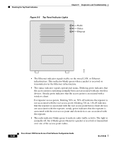
Checking the Top Panel Indicators Chapter 9 Diagnostics and Troubleshooting Figure 9-9 Top Panel Indicator Lights Radio Status Ethernet 74046 • The Ethernet indicator signals traffic on the wired LAN, or Ethernet infrastructure. This indicator blinks green when a packet is received or transmitted over the Ethernet infrastructure. • The status indicator signals operational status. Blinking green indicates that the access point is operating normally but is not associated with any wireless devices. Steady green indicates that the access point is associated with a wireless client. For repeater access points, blinking 50% on, 50% off indicates the repeater is not associated with the root access point; blinking 7/8 on, 1/8 off indicates that the repeater is associated with the root access point but no client devices are associated with the repeater; steady green indicates that the repeater is associated with the root access point and client devices are associated with the repeater. • The radio indicator blinks green to indicate radio traffic activity. The light is normally off, but it blinks green whenever a packet is received or transmitted over one of the access point radios. 9-38 Cisco Aironet 1200 Series Access Point Software Configuration Guide OL-2159-03
-
 1
1 -
2
-
3
-
4
-
5
-
6
-
7
-
8
-
9
-
10
-
11
-
12
-
13
-
14
-
15
-
16
-
17
-
18
-
19
-
20
-
21
-
22
-
23
-
24
-
25
-
26
-
27
-
28
-
29
-
30
-
31
-
32
-
33
-
34
-
35
-
36
-
37
-
38
-
39
-
40
-
41
-
42
-
43
-
44
-
45
-
46
-
47
-
48
-
49
-
50
-
51
-
52
-
53
-
54
-
55
-
56
-
57
-
58
-
59
-
60
-
61
-
62
-
63
-
64
-
65
-
66
-
67
-
68
-
69
-
70
-
71
-
72
-
73
-
74
-
75
-
76
-
77
-
78
-
79
-
80
-
81
-
82
-
83
-
84
-
85
-
86
-
87
-
88
-
89
-
90
-
91
-
92
-
93
-
94
-
95
-
96
-
97
-
98
-
99
-
100
-
101
-
102
-
103
-
104
-
105
-
106
-
107
-
108
-
109
-
110
-
111
-
112
-
113
-
114
-
115
-
116
-
117
-
118
-
119
-
120
-
121
-
122
-
123
-
124
-
125
-
126
-
127
-
128
-
129
-
130
-
131
-
132
-
133
-
134
-
135
-
136
-
137
-
138
-
139
-
140
-
141
-
142
-
143
-
144
-
145
-
146
-
147
-
148
-
149
-
150
-
151
-
152
-
153
-
154
-
155
-
156
-
157
-
158
-
159
-
160
-
161
-
162
-
163
-
164
-
165
-
166
-
167
-
168
-
169
-
170
-
171
-
172
-
173
-
174
-
175
-
176
-
177
-
178
-
179
-
180
-
181
-
182
-
183
-
184
-
185
-
186
-
187
-
188
-
189
-
190
-
191
-
192
-
193
-
194
-
195
-
196
-
197
-
198
-
199
-
200
-
201
-
202
-
203
-
204
-
205
-
206
-
207
-
208
-
209
-
210
-
211
-
212
-
213
-
214
-
215
-
216
-
217
-
218
-
219
-
220
-
221
-
222
-
223
-
224
-
225
-
226
-
227
-
228
-
229
-
230
-
231
-
232
-
233
-
234
-
235
-
236
-
237
-
238
-
239
-
240
-
241
-
242
-
243
-
244
-
245
-
246
-
247
-
248
-
249
-
250
-
 251
251 -
 252
252 -
 253
253 -
 254
254 -
 255
255 -
 256
256 -
 257
257 -
 258
258 -
 259
259 -
 260
260 -
 261
261 -
262
-
263
-
264
-
265
-
266
-
267
-
268
-
269
-
270
-
271
-
272
-
273
-
274
-
275
-
276
-
277
-
278
-
279
-
280
-
281
-
282
-
283
-
284
 |
 |
