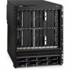
Dell PowerConnect B - MLXe 16 Hardware Installation Guide - Page 182
Replacing the fan tray assembly in 4-slot and 8-slot routers,
 |
View all Dell PowerConnect B - MLXe 16 manuals
Add to My Manuals
Save this manual to your list of manuals |
Page 182 highlights
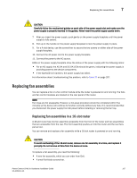
7 Replacing fan assemblies 6. Access the CLI, and enter the show chassis command to verify that the fans are operating normally. Replacing the fan tray assembly in 4-slot and 8-slot routers 4-slot and 8-slot routers have a fan tray assembly that is accessible from the front of the device. The fan tray assembly pulls air out of the device. You can remove and replace a fan tray assembly while the router is powered on and running. To replace a fan tray assembly, have these items available: • A new fan tray assembly, which you can order from Dell. • An ESD wrist strap with a plug for connection to the ESD connector on the router. DANGER For safety reasons, the ESD wrist strap should contain a 1 megohm series resistor. Follow these steps to replace a fan tray assembly in 4-slot and 8-slot routers. 1. Put on the ESD wrist strap and ground yourself by inserting the plug into the ESD connector located on the front of the router. 2. To remove the fan tray assembly from the router, grasp the handle and pull it toward you as shown in Figure 67 and Figure 68. Pulling the assembly unseats the fan tray assembly connector from a router connector. DANGER Be careful not to insert your fingers into the fan while removing it. The fan may still be spinning at a high speed. FIGURE 67 Removing a fan tray assembly from a 4-slot router. 170 PowerConnect B-MLXe Hardware Installation Guide 53-1002111-01
-
 1
1 -
2
-
3
-
4
-
5
-
6
-
7
-
8
-
9
-
10
-
11
-
12
-
13
-
14
-
15
-
16
-
17
-
18
-
19
-
20
-
21
-
22
-
23
-
24
-
25
-
26
-
27
-
28
-
29
-
30
-
31
-
32
-
33
-
34
-
35
-
36
-
37
-
38
-
39
-
40
-
41
-
42
-
43
-
44
-
45
-
46
-
47
-
48
-
49
-
50
-
51
-
52
-
53
-
54
-
55
-
56
-
57
-
58
-
59
-
60
-
61
-
62
-
63
-
64
-
65
-
66
-
67
-
68
-
69
-
70
-
71
-
72
-
73
-
74
-
75
-
76
-
77
-
78
-
79
-
80
-
81
-
82
-
83
-
84
-
85
-
86
-
87
-
88
-
89
-
90
-
91
-
92
-
93
-
94
-
95
-
96
-
97
-
98
-
99
-
100
-
101
-
102
-
103
-
104
-
105
-
106
-
107
-
108
-
109
-
110
-
111
-
112
-
113
-
114
-
115
-
116
-
117
-
118
-
119
-
120
-
121
-
122
-
123
-
124
-
125
-
126
-
127
-
128
-
129
-
130
-
131
-
132
-
133
-
134
-
135
-
136
-
137
-
138
-
139
-
140
-
141
-
142
-
143
-
144
-
145
-
146
-
147
-
148
-
149
-
150
-
151
-
152
-
153
-
154
-
155
-
156
-
157
-
158
-
159
-
160
-
161
-
162
-
163
-
164
-
165
-
166
-
167
-
168
-
169
-
170
-
171
-
172
-
173
-
174
-
175
-
176
-
 177
177 -
 178
178 -
 179
179 -
 180
180 -
 181
181 -
 182
182 -
 183
183 -
 184
184 -
 185
185 -
 186
186 -
 187
187 -
188
-
189
-
190
-
191
-
192
-
193
-
194
-
195
-
196
-
197
-
198
-
199
-
200
-
201
-
202
-
203
-
204
-
205
-
206
-
207
-
208
-
209
-
210
-
211
-
212
 |
 |
