Dell PowerConnect B - MLXe 16 Hardware Installation Guide - Page 20
Interface modules, Gbps Ethernet interface modules 4-port
 |
View all Dell PowerConnect B - MLXe 16 manuals
Add to My Manuals
Save this manual to your list of manuals |
Page 20 highlights
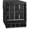
1 Router modules TABLE 2 LED Management module LEDs Position State Meaning Port 1 and Port 2 Active Pwr 10/100/1000 Ethernet Port 10/100/1000 Ethernet Port Each adjacent to the PCMCIA slot that it represents Lower Left Upper Left Above and right of RJ45 connector Above and left of RJ45 connector On or blinking Off On Off On Off On (Green) Off On or blinking (Yellow) Off for an extended period The software is currently accessing the PCMCIA flash card. The software is not currently accessing a PCMCIA flash card, although there is one inserted in the slot. The module is functioning as the active management module. The module is functioning as the redundant management module. The module is receiving power. The module is not receiving power. A link is established with the remote port. No link is established with the remote port. The port is transmitting and receiving packets. The port is not transmitting or receiving packets. Interface modules Table 3 lists the interface modules that are available for PowerConnect B-MLXe routers. TABLE 3 Interface modules Part Number Description DL-MLX-10Gx4-X-ML DL-MLX-1GFx24-X-ML DL-MLX-1GCx24-X-ML DL-NI-MLX-10Gx8-M DL-NI-MLX-10Gx8-D 4-port 10 Gbps Ethernet module with IPv4, IPv6, and MPLS hardware support--requires XFP optics 24-port FE or GE (100/1000) module with IPv4, IPv6, and MPLS hardware support--requires SFP optics 24-port 10/100/1000 copper modules with IPv4, IPv6, and MPLS hardware support Depending on your router model, you can install up to 16 interface modules. Interface modules are hot-swappable, which means you can remove and replace them without powering down the system. 10 Gbps Ethernet interface modules (4-port) Figure 5 shows 4-port 10 Gbps Ethernet interface module front panels. 8 PowerConnect B-MLXe Hardware Installation Guide 53-1002111-01
-
 1
1 -
2
-
3
-
4
-
5
-
6
-
7
-
8
-
9
-
10
-
11
-
12
-
13
-
14
-
 15
15 -
 16
16 -
 17
17 -
 18
18 -
 19
19 -
 20
20 -
 21
21 -
 22
22 -
 23
23 -
 24
24 -
 25
25 -
26
-
27
-
28
-
29
-
30
-
31
-
32
-
33
-
34
-
35
-
36
-
37
-
38
-
39
-
40
-
41
-
42
-
43
-
44
-
45
-
46
-
47
-
48
-
49
-
50
-
51
-
52
-
53
-
54
-
55
-
56
-
57
-
58
-
59
-
60
-
61
-
62
-
63
-
64
-
65
-
66
-
67
-
68
-
69
-
70
-
71
-
72
-
73
-
74
-
75
-
76
-
77
-
78
-
79
-
80
-
81
-
82
-
83
-
84
-
85
-
86
-
87
-
88
-
89
-
90
-
91
-
92
-
93
-
94
-
95
-
96
-
97
-
98
-
99
-
100
-
101
-
102
-
103
-
104
-
105
-
106
-
107
-
108
-
109
-
110
-
111
-
112
-
113
-
114
-
115
-
116
-
117
-
118
-
119
-
120
-
121
-
122
-
123
-
124
-
125
-
126
-
127
-
128
-
129
-
130
-
131
-
132
-
133
-
134
-
135
-
136
-
137
-
138
-
139
-
140
-
141
-
142
-
143
-
144
-
145
-
146
-
147
-
148
-
149
-
150
-
151
-
152
-
153
-
154
-
155
-
156
-
157
-
158
-
159
-
160
-
161
-
162
-
163
-
164
-
165
-
166
-
167
-
168
-
169
-
170
-
171
-
172
-
173
-
174
-
175
-
176
-
177
-
178
-
179
-
180
-
181
-
182
-
183
-
184
-
185
-
186
-
187
-
188
-
189
-
190
-
191
-
192
-
193
-
194
-
195
-
196
-
197
-
198
-
199
-
200
-
201
-
202
-
203
-
204
-
205
-
206
-
207
-
208
-
209
-
210
-
211
-
212
 |
 |
