Dell PowerConnect B - MLXe 16 Hardware Installation Guide - Page 75
TABLE 15, PowerConnect B-MLXe-16 module slot designations - powerconnect b brocade mlxe 16
 |
View all Dell PowerConnect B - MLXe 16 manuals
Add to My Manuals
Save this manual to your list of manuals |
Page 75 highlights
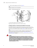
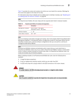
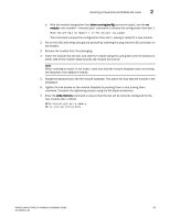
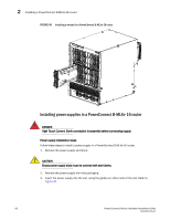
Installing a PowerConnect B-MLXe-16 router 2 Table 15 provides the router slot numbers into which you must install the modules. Markings for the router slots appear at the base of the slots. For information about how to disable and re-enable power to interface modules, see "Disabling and re-enabling power to interface modules" on page 99 NOTE The PowerConnect B-MLXe-16 router ships with the required switch fabric modules installed. TABLE 15 Module PowerConnect B-MLXe-16 module slot designations Slot number Management modules Interface modules Switch Fabric modules Active module - M1 (upper). Redundant module - M2 (lower). 1 - 16 SF1 - SF4 NOTE If you are installing a redundant management module, refer to the chapter titled "Using a Redundant Management Module" in the Brocade NetIron Configuration Guide for information about how the redundant module works, optional software configurations that you can perform, and how to manage the redundancy feature. NOTE PowerConnect B-MLXe modules are dedicated, which means that you must install them in PowerConnect B-MLXe routers only. If you install a PowerConnect B-MLXe module in another Dell router or install a module intended for another Dell router in a PowerConnect B-MLXe router, the router and module may not function properly. Before installing modules in the PowerConnect B-MLXe-16 router, have the following items available: • A large flat-blade screwdriver. • A new or replacement interface module, which you can order from Dell • An ESD wrist strap with a plug to attach to the ESD connector on the router chassis. DANGER For safety reasons, the ESD wrist strap should contain a 1 megohm series resistor. CAUTION Use of a power screwdriver may twist the heads from the screws and is not recommended. PowerConnect B-MLXe Hardware Installation Guide 63 53-1002111-01
-
 1
1 -
2
-
3
-
4
-
5
-
6
-
7
-
8
-
9
-
10
-
11
-
12
-
13
-
14
-
15
-
16
-
17
-
18
-
19
-
20
-
21
-
22
-
23
-
24
-
25
-
26
-
27
-
28
-
29
-
30
-
31
-
32
-
33
-
34
-
35
-
36
-
37
-
38
-
39
-
40
-
41
-
42
-
43
-
44
-
45
-
46
-
47
-
48
-
49
-
50
-
51
-
52
-
53
-
54
-
55
-
56
-
57
-
58
-
59
-
60
-
61
-
62
-
63
-
64
-
65
-
66
-
67
-
68
-
69
-
 70
70 -
 71
71 -
 72
72 -
 73
73 -
 74
74 -
 75
75 -
 76
76 -
 77
77 -
 78
78 -
 79
79 -
 80
80 -
81
-
82
-
83
-
84
-
85
-
86
-
87
-
88
-
89
-
90
-
91
-
92
-
93
-
94
-
95
-
96
-
97
-
98
-
99
-
100
-
101
-
102
-
103
-
104
-
105
-
106
-
107
-
108
-
109
-
110
-
111
-
112
-
113
-
114
-
115
-
116
-
117
-
118
-
119
-
120
-
121
-
122
-
123
-
124
-
125
-
126
-
127
-
128
-
129
-
130
-
131
-
132
-
133
-
134
-
135
-
136
-
137
-
138
-
139
-
140
-
141
-
142
-
143
-
144
-
145
-
146
-
147
-
148
-
149
-
150
-
151
-
152
-
153
-
154
-
155
-
156
-
157
-
158
-
159
-
160
-
161
-
162
-
163
-
164
-
165
-
166
-
167
-
168
-
169
-
170
-
171
-
172
-
173
-
174
-
175
-
176
-
177
-
178
-
179
-
180
-
181
-
182
-
183
-
184
-
185
-
186
-
187
-
188
-
189
-
190
-
191
-
192
-
193
-
194
-
195
-
196
-
197
-
198
-
199
-
200
-
201
-
202
-
203
-
204
-
205
-
206
-
207
-
208
-
209
-
210
-
211
-
212
 |
 |
