Dell PowerConnect B - MLXe 16 Hardware Installation Guide - Page 82
Verifying proper operation, Observing the LEDs
 |
View all Dell PowerConnect B - MLXe 16 manuals
Add to My Manuals
Save this manual to your list of manuals |
Page 82 highlights
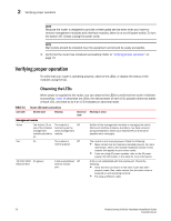
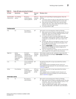
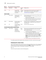
2 Verifying proper operation NOTE Because the router is designed to provide uninterrupted service even when you insert or remove management modules and interface modules, there is no on/off power switch. To turn the system off, simply unplug the power cords. NOTE Wall outlets should be installed near the equipment and should be easily accessible. 3. Verify that the router has initialized successfully. Refer to "Verifying proper operation" on page 70. Verifying proper operation To verify that your router is operating properly, observe the LEDs, or display the status of the modules using the CLI. Observing the LEDs TABLE 16 LED label When power is supplied to the router, you can observe the LEDs to verify that the router initialized successfully. Table 16 describes the LEDs, the desired state of each LED, possible abnormal states of each LED, and what to do if an LED indicates an abnormal state. Router LED states and actions Desired state Meaning Abnormal Meaning or action state Management module Active The Active LED on The module is Off one of the installed functioning as the management active management modules should be module. on. Pwr On The module is Off receiving power. 10/100/1000 On (green) Ethernet Port A link is established Off with the remote port. Neither of the management modules is managing the switch fabric and interface modules. A problem may have occurred during initialization. Check your attached PC or terminal for possible error messages. The module is not receiving power. Check the following: • Make certain that the module is installed properly. For more information, refer to the module installation section in this chapter that applies to your router model. • If you are using AC power supplies, refer to the AC power supply LED information in this table for more information. A link is not established with the remote port. Check the following: • Verify that the connection to the other router has been properly made. Also, make certain that the other router is powered on and operating correctly. • Try using a different cable. 70 PowerConnect B-MLXe Hardware Installation Guide 53-1002111-01
-
 1
1 -
2
-
3
-
4
-
5
-
6
-
7
-
8
-
9
-
10
-
11
-
12
-
13
-
14
-
15
-
16
-
17
-
18
-
19
-
20
-
21
-
22
-
23
-
24
-
25
-
26
-
27
-
28
-
29
-
30
-
31
-
32
-
33
-
34
-
35
-
36
-
37
-
38
-
39
-
40
-
41
-
42
-
43
-
44
-
45
-
46
-
47
-
48
-
49
-
50
-
51
-
52
-
53
-
54
-
55
-
56
-
57
-
58
-
59
-
60
-
61
-
62
-
63
-
64
-
65
-
66
-
67
-
68
-
69
-
70
-
71
-
72
-
73
-
74
-
75
-
76
-
 77
77 -
 78
78 -
 79
79 -
 80
80 -
 81
81 -
 82
82 -
 83
83 -
 84
84 -
 85
85 -
 86
86 -
 87
87 -
88
-
89
-
90
-
91
-
92
-
93
-
94
-
95
-
96
-
97
-
98
-
99
-
100
-
101
-
102
-
103
-
104
-
105
-
106
-
107
-
108
-
109
-
110
-
111
-
112
-
113
-
114
-
115
-
116
-
117
-
118
-
119
-
120
-
121
-
122
-
123
-
124
-
125
-
126
-
127
-
128
-
129
-
130
-
131
-
132
-
133
-
134
-
135
-
136
-
137
-
138
-
139
-
140
-
141
-
142
-
143
-
144
-
145
-
146
-
147
-
148
-
149
-
150
-
151
-
152
-
153
-
154
-
155
-
156
-
157
-
158
-
159
-
160
-
161
-
162
-
163
-
164
-
165
-
166
-
167
-
168
-
169
-
170
-
171
-
172
-
173
-
174
-
175
-
176
-
177
-
178
-
179
-
180
-
181
-
182
-
183
-
184
-
185
-
186
-
187
-
188
-
189
-
190
-
191
-
192
-
193
-
194
-
195
-
196
-
197
-
198
-
199
-
200
-
201
-
202
-
203
-
204
-
205
-
206
-
207
-
208
-
209
-
210
-
211
-
212
 |
 |
