Dell PowerConnect B - MLXe 16 Hardware Installation Guide - Page 52
Final steps, Installing a PowerConnect B-MLXe-8 router, Preparing the installation site
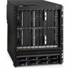 |
View all Dell PowerConnect B - MLXe 16 manuals
Add to My Manuals
Save this manual to your list of manuals |
Page 52 highlights
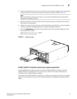
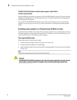
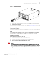
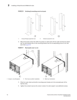
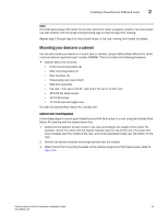
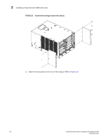
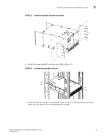
2 Installing a PowerConnect B-MLXe-8 router Final steps Complete these steps in the order listed: • "Attaching a management station" • "Activating the power source" • "Verifying proper operation" Installing a PowerConnect B-MLXe-8 router This section describes how to install a PowerConnect B-MLXe-8 router. NOTE Illustrations in this chapter may differ slightly from the actual equipment. Preparing the installation site Before installing the router, plan the location and orientation relative to other devices and equipment. For cooling purposes, allow a minimum of six inches of space between the sides, front, and the back of the router and walls or other obstructions. If a router is installed in a perforated enclosure, the perforations must cover at least 60 percent of the surface. NOTE This equipment is suitable for installation in a Network Telecommunication facility and where NEC requirements apply. Additionally, it may be installed in either a Common Bonding Network (CBN) or Isolated Bonding Network (IBN). It is not intended for Outside Plant (OSP) installations. Ensure that the proper cabling is installed at the site. For information on cabling, refer to "Installing power supplies in the PowerConnect B-MLXe-8 router" on page 51, "Attaching a management station" on page 68, and "Connecting the router to a network device" on page 95. Unpacking a PowerConnect B-MLXe-8 router The PowerConnect B-MLXe-8 router ships with the following items: • Switch fabric modules installed in slots marked SF, and slot blanks installed in all empty module slots. • Two AC power supplies • Insertion or extraction tool for use with RJ45 and fiber-optic connectors. Save the shipping carton and packing materials in case you need to move or ship the router at a later time. Lifting guidelines for PowerConnect B-MLXe-8 routers Follow these guidelines for lifting and moving PowerConnect B-MLXe-8 routers: • Before lifting or moving the router, disconnect all external cables. 40 PowerConnect B-MLXe Hardware Installation Guide 53-1002111-01
-
 1
1 -
2
-
3
-
4
-
5
-
6
-
7
-
8
-
9
-
10
-
11
-
12
-
13
-
14
-
15
-
16
-
17
-
18
-
19
-
20
-
21
-
22
-
23
-
24
-
25
-
26
-
27
-
28
-
29
-
30
-
31
-
32
-
33
-
34
-
35
-
36
-
37
-
38
-
39
-
40
-
41
-
42
-
43
-
44
-
45
-
46
-
 47
47 -
 48
48 -
 49
49 -
 50
50 -
 51
51 -
 52
52 -
 53
53 -
 54
54 -
 55
55 -
 56
56 -
 57
57 -
58
-
59
-
60
-
61
-
62
-
63
-
64
-
65
-
66
-
67
-
68
-
69
-
70
-
71
-
72
-
73
-
74
-
75
-
76
-
77
-
78
-
79
-
80
-
81
-
82
-
83
-
84
-
85
-
86
-
87
-
88
-
89
-
90
-
91
-
92
-
93
-
94
-
95
-
96
-
97
-
98
-
99
-
100
-
101
-
102
-
103
-
104
-
105
-
106
-
107
-
108
-
109
-
110
-
111
-
112
-
113
-
114
-
115
-
116
-
117
-
118
-
119
-
120
-
121
-
122
-
123
-
124
-
125
-
126
-
127
-
128
-
129
-
130
-
131
-
132
-
133
-
134
-
135
-
136
-
137
-
138
-
139
-
140
-
141
-
142
-
143
-
144
-
145
-
146
-
147
-
148
-
149
-
150
-
151
-
152
-
153
-
154
-
155
-
156
-
157
-
158
-
159
-
160
-
161
-
162
-
163
-
164
-
165
-
166
-
167
-
168
-
169
-
170
-
171
-
172
-
173
-
174
-
175
-
176
-
177
-
178
-
179
-
180
-
181
-
182
-
183
-
184
-
185
-
186
-
187
-
188
-
189
-
190
-
191
-
192
-
193
-
194
-
195
-
196
-
197
-
198
-
199
-
200
-
201
-
202
-
203
-
204
-
205
-
206
-
207
-
208
-
209
-
210
-
211
-
212
 |
 |
