Dell PowerConnect B - MLXe 16 Hardware Installation Guide - Page 191
Management port pin assignments, Power cords
 |
View all Dell PowerConnect B - MLXe 16 manuals
Add to My Manuals
Save this manual to your list of manuals |
Page 191 highlights
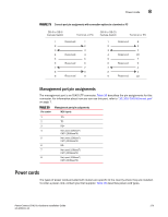
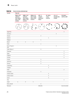
Power cords 8 FIGURE 73 Console port pin assignments with connection options to a terminal or PC DB-9 to DB-9 Female Switch Terminal or PC 1 Reserved 1 2 2 3 3 4 Reserved 4 5 5 6 Reserved 6 7 7 8 8 9 Reserved 9 DB-9 to DB-25 Female Switch Terminal or PC 1 Reserved 8 2 3 3 2 4 Reserved 20 5 7 6 Reserved 6 7 4 8 5 9 Reserved 22 Management port pin assignments The management port is an RJ45 UTP connector. Table 35 describes the pin assignments for this connector. For information about how you can use this port, refer to "10/100/1000 Ethernet port" on page 7. TABLE 35 Management port pin assignments Pin number MDI-X ports 1 TD+ 2 TD- 3 RD+ 4 Not used (10BaseT) CMT (100BaseTX) 5 Not used (10BaseT) CMT (100BaseTX) 6 RD- 7 Not used (10BaseT) CMT (100BaseTX) 8 Not used (10BaseT) CMT (100BaseTX) Power cords The types of power cords provided with routers are specific to the country where they are installed. To order a power cord, contact your Dell supplier. Table 36 describes power cord types. PowerConnect B-MLXe Hardware Installation Guide 179 53-1002111-01
-
 1
1 -
2
-
3
-
4
-
5
-
6
-
7
-
8
-
9
-
10
-
11
-
12
-
13
-
14
-
15
-
16
-
17
-
18
-
19
-
20
-
21
-
22
-
23
-
24
-
25
-
26
-
27
-
28
-
29
-
30
-
31
-
32
-
33
-
34
-
35
-
36
-
37
-
38
-
39
-
40
-
41
-
42
-
43
-
44
-
45
-
46
-
47
-
48
-
49
-
50
-
51
-
52
-
53
-
54
-
55
-
56
-
57
-
58
-
59
-
60
-
61
-
62
-
63
-
64
-
65
-
66
-
67
-
68
-
69
-
70
-
71
-
72
-
73
-
74
-
75
-
76
-
77
-
78
-
79
-
80
-
81
-
82
-
83
-
84
-
85
-
86
-
87
-
88
-
89
-
90
-
91
-
92
-
93
-
94
-
95
-
96
-
97
-
98
-
99
-
100
-
101
-
102
-
103
-
104
-
105
-
106
-
107
-
108
-
109
-
110
-
111
-
112
-
113
-
114
-
115
-
116
-
117
-
118
-
119
-
120
-
121
-
122
-
123
-
124
-
125
-
126
-
127
-
128
-
129
-
130
-
131
-
132
-
133
-
134
-
135
-
136
-
137
-
138
-
139
-
140
-
141
-
142
-
143
-
144
-
145
-
146
-
147
-
148
-
149
-
150
-
151
-
152
-
153
-
154
-
155
-
156
-
157
-
158
-
159
-
160
-
161
-
162
-
163
-
164
-
165
-
166
-
167
-
168
-
169
-
170
-
171
-
172
-
173
-
174
-
175
-
176
-
177
-
178
-
179
-
180
-
181
-
182
-
183
-
184
-
185
-
 186
186 -
 187
187 -
 188
188 -
 189
189 -
 190
190 -
 191
191 -
 192
192 -
 193
193 -
 194
194 -
 195
195 -
 196
196 -
197
-
198
-
199
-
200
-
201
-
202
-
203
-
204
-
205
-
206
-
207
-
208
-
209
-
210
-
211
-
212
 |
 |
