Dell PowerConnect B - MLXe 16 Hardware Installation Guide - Page 49
NI-MLX-1Gx48-T-A interface module power supply requirements,
 |
View all Dell PowerConnect B - MLXe 16 manuals
Add to My Manuals
Save this manual to your list of manuals |
Page 49 highlights
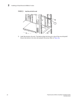
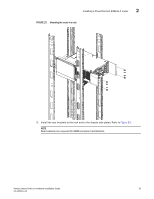
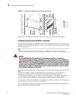
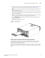
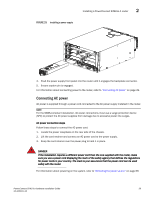
Installing a PowerConnect B-MLXe-4 router 2 4. Insert the module into the router slot, and slide the card along the card guide until the ejectors on either side of the module move close to the module front panel. Refer to Figure 24. NOTE When inserting the module into the router, be sure that the faceplate does not overlap the faceplate of an adjacent module. 5. Rotate the ejectors until they are flush with the module front panel. This action will fully seat the module in the backplane. 6. Tighten the screws at each end of the module faceplate by pushing them in and turning them clockwise. Complete the tightening process using the flat-blade screwdriver. 7. Enter the write memory command to ensure that the slot will be correctly configured for the new module after a reboot. PowerConnect(config)# write memory Write startup-config done. FIGURE 24 Installing a module NI-MLX-1Gx48-T-A interface module power supply requirements A single 1200W power supply will support up to three NI-MLX-1Gx48-T-A modules, with other modules filling the remaining slots. You can equip your router for 1+2 power redundancy by installing up to two additional power supplies. If you install four NI-MLX-1Gx48-T-A modules in your router, you will need a minimum of two power supplies. You can equip your router for 2+1 power redundancy by installing one additional power supply. PowerConnect B-MLXe Hardware Installation Guide 37 53-1002111-01
-
 1
1 -
2
-
3
-
4
-
5
-
6
-
7
-
8
-
9
-
10
-
11
-
12
-
13
-
14
-
15
-
16
-
17
-
18
-
19
-
20
-
21
-
22
-
23
-
24
-
25
-
26
-
27
-
28
-
29
-
30
-
31
-
32
-
33
-
34
-
35
-
36
-
37
-
38
-
39
-
40
-
41
-
42
-
43
-
 44
44 -
 45
45 -
 46
46 -
 47
47 -
 48
48 -
 49
49 -
 50
50 -
 51
51 -
 52
52 -
 53
53 -
 54
54 -
55
-
56
-
57
-
58
-
59
-
60
-
61
-
62
-
63
-
64
-
65
-
66
-
67
-
68
-
69
-
70
-
71
-
72
-
73
-
74
-
75
-
76
-
77
-
78
-
79
-
80
-
81
-
82
-
83
-
84
-
85
-
86
-
87
-
88
-
89
-
90
-
91
-
92
-
93
-
94
-
95
-
96
-
97
-
98
-
99
-
100
-
101
-
102
-
103
-
104
-
105
-
106
-
107
-
108
-
109
-
110
-
111
-
112
-
113
-
114
-
115
-
116
-
117
-
118
-
119
-
120
-
121
-
122
-
123
-
124
-
125
-
126
-
127
-
128
-
129
-
130
-
131
-
132
-
133
-
134
-
135
-
136
-
137
-
138
-
139
-
140
-
141
-
142
-
143
-
144
-
145
-
146
-
147
-
148
-
149
-
150
-
151
-
152
-
153
-
154
-
155
-
156
-
157
-
158
-
159
-
160
-
161
-
162
-
163
-
164
-
165
-
166
-
167
-
168
-
169
-
170
-
171
-
172
-
173
-
174
-
175
-
176
-
177
-
178
-
179
-
180
-
181
-
182
-
183
-
184
-
185
-
186
-
187
-
188
-
189
-
190
-
191
-
192
-
193
-
194
-
195
-
196
-
197
-
198
-
199
-
200
-
201
-
202
-
203
-
204
-
205
-
206
-
207
-
208
-
209
-
210
-
211
-
212
 |
 |
