Dell PowerConnect B - MLXe 16 Hardware Installation Guide - Page 81
Activating the power source
 |
View all Dell PowerConnect B - MLXe 16 manuals
Add to My Manuals
Save this manual to your list of manuals |
Page 81 highlights
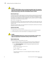
Activating the power source 2 • For console port connections, a straight-through EIA or TIA DB-9 serial cable with one end terminated in a female DB-9 connector and the other end terminated in a male or female DB-9 or DB-25 connector, depending on the specifications of your PC or terminal. You can order this cable from Dell or build your own cable. If you build your own cable, refer to the pinout information in "Console port pin assignments" on page 178. • For Ethernet port connections, a Category 5 UTP crossover cable, which you must supply. For information about the management port pin assignments, refer to "Management port pin assignments" on page 179. PC or terminal to console or Ethernet port connection steps Follow these steps to attach a PC or terminal to the console port or Ethernet port. 1. Connect a PC or terminal to the console port or Ethernet port using the appropriate cable. 2. Open the terminal emulation program, and set the session parameters as follows: • Baud: 9600 bps • Data bits: 8 • Parity: None • Stop bits: 1 • Flow control: None Activating the power source When you complete the hardware installation, you are ready to activate the power source. Power source activation steps 1. Verify that all modules and power supplies are properly installed and all empty slots are covered by slot blanks. CAUTION If you do not install a module in a slot, you must keep the slot blank in place. If you run the router with an uncovered slot, the system may overheat. 2. If you are supplying AC power to your router, attach one end of an AC power cord to each installed AC power supply as described in the appropriate section: • "Connecting AC power" on page 67 Insert the other end of each cable into a 115V/120V wall outlet. DANGER If the installation requires a different power cord than the one supplied with the router, make sure you use a power cord displaying the mark of the safety agency that defines the regulations for power cords in your country. The mark is your assurance that the power cord can be used safely with the router. PowerConnect B-MLXe Hardware Installation Guide 69 53-1002111-01
-
 1
1 -
2
-
3
-
4
-
5
-
6
-
7
-
8
-
9
-
10
-
11
-
12
-
13
-
14
-
15
-
16
-
17
-
18
-
19
-
20
-
21
-
22
-
23
-
24
-
25
-
26
-
27
-
28
-
29
-
30
-
31
-
32
-
33
-
34
-
35
-
36
-
37
-
38
-
39
-
40
-
41
-
42
-
43
-
44
-
45
-
46
-
47
-
48
-
49
-
50
-
51
-
52
-
53
-
54
-
55
-
56
-
57
-
58
-
59
-
60
-
61
-
62
-
63
-
64
-
65
-
66
-
67
-
68
-
69
-
70
-
71
-
72
-
73
-
74
-
75
-
 76
76 -
 77
77 -
 78
78 -
 79
79 -
 80
80 -
 81
81 -
 82
82 -
 83
83 -
 84
84 -
 85
85 -
 86
86 -
87
-
88
-
89
-
90
-
91
-
92
-
93
-
94
-
95
-
96
-
97
-
98
-
99
-
100
-
101
-
102
-
103
-
104
-
105
-
106
-
107
-
108
-
109
-
110
-
111
-
112
-
113
-
114
-
115
-
116
-
117
-
118
-
119
-
120
-
121
-
122
-
123
-
124
-
125
-
126
-
127
-
128
-
129
-
130
-
131
-
132
-
133
-
134
-
135
-
136
-
137
-
138
-
139
-
140
-
141
-
142
-
143
-
144
-
145
-
146
-
147
-
148
-
149
-
150
-
151
-
152
-
153
-
154
-
155
-
156
-
157
-
158
-
159
-
160
-
161
-
162
-
163
-
164
-
165
-
166
-
167
-
168
-
169
-
170
-
171
-
172
-
173
-
174
-
175
-
176
-
177
-
178
-
179
-
180
-
181
-
182
-
183
-
184
-
185
-
186
-
187
-
188
-
189
-
190
-
191
-
192
-
193
-
194
-
195
-
196
-
197
-
198
-
199
-
200
-
201
-
202
-
203
-
204
-
205
-
206
-
207
-
208
-
209
-
210
-
211
-
212
 |
 |
