Dell PowerConnect B - MLXe 16 Hardware Installation Guide - Page 46
Installing PowerConnect B-MLXe-4 modules,
 |
View all Dell PowerConnect B - MLXe 16 manuals
Add to My Manuals
Save this manual to your list of manuals |
Page 46 highlights
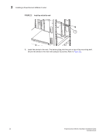
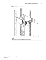
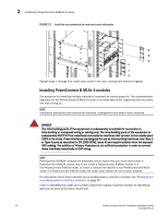
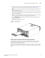
2 Installing a PowerConnect B-MLXe-4 router FIGURE 23 Install the rear brackets to the rack and chassis side plates Repeat steps 2 through 8 to install each router in the rack, moving from lowest to highest. Installing PowerConnect B-MLXe-4 modules The sequence for installing multiple modules is important to ensure proper fit. The recommended sequence for the PowerConnect B-MLXe-4 router is to install right-to-left, beginning with the lowest row and moving up. NOTE Installation procedures are identical for interface, management and switch fabric modules. DANGER The intra-building ports of the equipment or subassembly is suitable for connection to intra-building or unexposed wiring or cabling only. The intra-building ports of the equipment or subassembly MUST NOT be metallically connected to interfaces that connect to the outside plant (OSP) or its wiring. These interfaces are designed for use as intra-building interfaces only (Type 2 or Type 4 ports as described in GR-1089-CORE, Issue 4) and require isolation from the exposed OSP cabling. The addition of Primary Protectors is not sufficient protection in order to connect these interfaces metallically to OSP wiring. NOTE PowerConnect B-MLXe modules are dedicated, which means that you must install them in PowerConnect B-MLXe routers only. If you install a PowerConnect B-MLXe module in a non-PowerConnect B-MLXe router, or install a module intended for a non-PowerConnect B-MLXe router in a PowerConnect B-MLXe router, the router and module will not function properly. For information about how to disable and re-enable power to interface modules, see "Disabling and re-enabling power to interface modules" on page 99 Table 13 identifies the router slot numbers where the modules must be installed. An identifying label can be seen at the base of each slot. 34 PowerConnect B-MLXe Hardware Installation Guide 53-1002111-01
-
 1
1 -
2
-
3
-
4
-
5
-
6
-
7
-
8
-
9
-
10
-
11
-
12
-
13
-
14
-
15
-
16
-
17
-
18
-
19
-
20
-
21
-
22
-
23
-
24
-
25
-
26
-
27
-
28
-
29
-
30
-
31
-
32
-
33
-
34
-
35
-
36
-
37
-
38
-
39
-
40
-
 41
41 -
 42
42 -
 43
43 -
 44
44 -
 45
45 -
 46
46 -
 47
47 -
 48
48 -
 49
49 -
 50
50 -
 51
51 -
52
-
53
-
54
-
55
-
56
-
57
-
58
-
59
-
60
-
61
-
62
-
63
-
64
-
65
-
66
-
67
-
68
-
69
-
70
-
71
-
72
-
73
-
74
-
75
-
76
-
77
-
78
-
79
-
80
-
81
-
82
-
83
-
84
-
85
-
86
-
87
-
88
-
89
-
90
-
91
-
92
-
93
-
94
-
95
-
96
-
97
-
98
-
99
-
100
-
101
-
102
-
103
-
104
-
105
-
106
-
107
-
108
-
109
-
110
-
111
-
112
-
113
-
114
-
115
-
116
-
117
-
118
-
119
-
120
-
121
-
122
-
123
-
124
-
125
-
126
-
127
-
128
-
129
-
130
-
131
-
132
-
133
-
134
-
135
-
136
-
137
-
138
-
139
-
140
-
141
-
142
-
143
-
144
-
145
-
146
-
147
-
148
-
149
-
150
-
151
-
152
-
153
-
154
-
155
-
156
-
157
-
158
-
159
-
160
-
161
-
162
-
163
-
164
-
165
-
166
-
167
-
168
-
169
-
170
-
171
-
172
-
173
-
174
-
175
-
176
-
177
-
178
-
179
-
180
-
181
-
182
-
183
-
184
-
185
-
186
-
187
-
188
-
189
-
190
-
191
-
192
-
193
-
194
-
195
-
196
-
197
-
198
-
199
-
200
-
201
-
202
-
203
-
204
-
205
-
206
-
207
-
208
-
209
-
210
-
211
-
212
 |
 |
