Dell PowerConnect B - MLXe 16 Hardware Installation Guide - Page 74
Installing modules in a PowerConnect B-MLXe 16-slot router,
 |
View all Dell PowerConnect B - MLXe 16 manuals
Add to My Manuals
Save this manual to your list of manuals |
Page 74 highlights
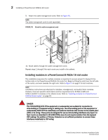
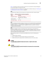
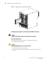
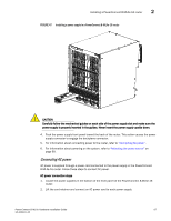
2 Installing a PowerConnect B-MLXe-16 router 9. Attach the cable management comb. Refer to Figure 45. NOTE The cable managment comb is sold separately. FIGURE 45 Attach the cable management comb 10. Route cables through the cable management comb. Repeat steps 1 through 9 for each router you install in the cabinet. Installing modules in a PowerConnect B-MLXe 16-slot router The installation sequence for multiple modules is important to ensure proper fit. Always fill the bottom slots in the PowerConnect B-MLXe-16 router first. Begin by filling the slots from the left side of the router, and work towards the right side. Refer to Figure 3 on page 4 for slot locations. NOTE Installation instructions are identical for interface, management, and switch fabric modules. However, there are specific switch fabric and fan requirements for NI-MLX-10x8G and NI-MLX-1Gx48-T-A modules in the 16-slot router. Refer to "Installing modules in a PowerConnect B-MLXe 16-slot router" on page 62. DANGER The intra-building ports of the equipment or subassembly are suitable for connection to intra-building or unexposed wiring or cabling only. The intra-building ports of the equipment or subassembly MUST NOT be metallically connected to interfaces that connect to the outside plant (OSP) or its wiring. These ports are designed for use as intra-building interfaces only (Type 2 or Type 4 ports as described in GR-1089-CORE, Issue 4) and require isolation from the exposed OSP cabling. The addition of Primary Protectors is not sufficient protection to connect these interfaces metallically to OSP wiring. 62 PowerConnect B-MLXe Hardware Installation Guide 53-1002111-01
-
 1
1 -
2
-
3
-
4
-
5
-
6
-
7
-
8
-
9
-
10
-
11
-
12
-
13
-
14
-
15
-
16
-
17
-
18
-
19
-
20
-
21
-
22
-
23
-
24
-
25
-
26
-
27
-
28
-
29
-
30
-
31
-
32
-
33
-
34
-
35
-
36
-
37
-
38
-
39
-
40
-
41
-
42
-
43
-
44
-
45
-
46
-
47
-
48
-
49
-
50
-
51
-
52
-
53
-
54
-
55
-
56
-
57
-
58
-
59
-
60
-
61
-
62
-
63
-
64
-
65
-
66
-
67
-
68
-
 69
69 -
 70
70 -
 71
71 -
 72
72 -
 73
73 -
 74
74 -
 75
75 -
 76
76 -
 77
77 -
 78
78 -
 79
79 -
80
-
81
-
82
-
83
-
84
-
85
-
86
-
87
-
88
-
89
-
90
-
91
-
92
-
93
-
94
-
95
-
96
-
97
-
98
-
99
-
100
-
101
-
102
-
103
-
104
-
105
-
106
-
107
-
108
-
109
-
110
-
111
-
112
-
113
-
114
-
115
-
116
-
117
-
118
-
119
-
120
-
121
-
122
-
123
-
124
-
125
-
126
-
127
-
128
-
129
-
130
-
131
-
132
-
133
-
134
-
135
-
136
-
137
-
138
-
139
-
140
-
141
-
142
-
143
-
144
-
145
-
146
-
147
-
148
-
149
-
150
-
151
-
152
-
153
-
154
-
155
-
156
-
157
-
158
-
159
-
160
-
161
-
162
-
163
-
164
-
165
-
166
-
167
-
168
-
169
-
170
-
171
-
172
-
173
-
174
-
175
-
176
-
177
-
178
-
179
-
180
-
181
-
182
-
183
-
184
-
185
-
186
-
187
-
188
-
189
-
190
-
191
-
192
-
193
-
194
-
195
-
196
-
197
-
198
-
199
-
200
-
201
-
202
-
203
-
204
-
205
-
206
-
207
-
208
-
209
-
210
-
211
-
212
 |
 |
