Dell PowerConnect J-8208 Hardware Guide - Page 106
Unpacking a J-EX8200 Switch
 |
View all Dell PowerConnect J-8208 manuals
Add to My Manuals
Save this manual to your list of manuals |
Page 106 highlights
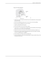
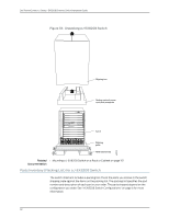
Dell PowerConnect J-Series J-EX8208 Ethernet Switch Hardware Guide To connect the switch to a network for out-of-band management, follow instructions in "Connecting a J-EX Series Switch to a Network for Out-of-Band Management" on page 140. To connect the switch to a management console, follow instructions in "Connecting a J-EX Series Switch to a Management Console" on page 135. Related • Rack Requirements for a J-EX8208 Switch on page 63 Documentation • Cabinet Requirements and Specifications for a J-EX8208 Switch on page 66 • Clearance Requirements for Airflow and Hardware Maintenance for a J-EX8208 Switch on page 67 • Chassis Lifting Guidelines for J-EX8200 Switches on page 220 Unpacking a J-EX8200 Switch After you prepare the installation site as described in "Site Preparation Checklist for a J-EX8200 Switch" on page 57, you may unpack the switch. NOTE: The switch is maximally protected inside the shipping box. Do not unpack it until you are ready to begin installation. Ensure that you have the following parts and tools available to unpack the J-EX8200 switch: • A 7/16-in. or 11-mm open-end or socket wrench to remove the bracket bolts from the shipping pallet • A box cutter or packing knife to slice open the tape that seals the top of the box The switch ships in a cardboard box that has a two-layer wooden pallet base with foam cushioning between the layers. The switch chassis is bolted to the pallet base. The J-EX8208 chassis ships with the Switch Fabric and Routing Engine (SRE) modules, Switch Fabric (SF) module, fan tray, and power supplies for the configuration you ordered already installed. Any line cards ordered ship separately. To unpack the switch (see Figure 33 on page 92): 1. Move the shipping box to a staging area as close to the installation site as possible. For a J-EX8208 switch, make sure there is enough space to remove components from the chassis if necessary (for example, if you do not have a mechanical lift to use when you install the switch). While the chassis is bolted to the pallet, you can use a forklift or pallet jack to move it. 2. Position the shipping box with the arrows pointing up. 3. Open the four pallet fasteners near the bottom of the shipping box that attach the cardboard box to the wooden pallet. To open a pallet fastener, squeeze together the two ridges ("fins") in the depression in the latch, then slide the pallet fastener out of the cardboard box slot in which it is inserted. See Figure 32 on page 91. 90
-
 1
1 -
2
-
3
-
4
-
5
-
6
-
7
-
8
-
9
-
10
-
11
-
12
-
13
-
14
-
15
-
16
-
17
-
18
-
19
-
20
-
21
-
22
-
23
-
24
-
25
-
26
-
27
-
28
-
29
-
30
-
31
-
32
-
33
-
34
-
35
-
36
-
37
-
38
-
39
-
40
-
41
-
42
-
43
-
44
-
45
-
46
-
47
-
48
-
49
-
50
-
51
-
52
-
53
-
54
-
55
-
56
-
57
-
58
-
59
-
60
-
61
-
62
-
63
-
64
-
65
-
66
-
67
-
68
-
69
-
70
-
71
-
72
-
73
-
74
-
75
-
76
-
77
-
78
-
79
-
80
-
81
-
82
-
83
-
84
-
85
-
86
-
87
-
88
-
89
-
90
-
91
-
92
-
93
-
94
-
95
-
96
-
97
-
98
-
99
-
100
-
 101
101 -
 102
102 -
 103
103 -
 104
104 -
 105
105 -
 106
106 -
 107
107 -
 108
108 -
 109
109 -
 110
110 -
 111
111 -
112
-
113
-
114
-
115
-
116
-
117
-
118
-
119
-
120
-
121
-
122
-
123
-
124
-
125
-
126
-
127
-
128
-
129
-
130
-
131
-
132
-
133
-
134
-
135
-
136
-
137
-
138
-
139
-
140
-
141
-
142
-
143
-
144
-
145
-
146
-
147
-
148
-
149
-
150
-
151
-
152
-
153
-
154
-
155
-
156
-
157
-
158
-
159
-
160
-
161
-
162
-
163
-
164
-
165
-
166
-
167
-
168
-
169
-
170
-
171
-
172
-
173
-
174
-
175
-
176
-
177
-
178
-
179
-
180
-
181
-
182
-
183
-
184
-
185
-
186
-
187
-
188
-
189
-
190
-
191
-
192
-
193
-
194
-
195
-
196
-
197
-
198
-
199
-
200
-
201
-
202
-
203
-
204
-
205
-
206
-
207
-
208
-
209
-
210
-
211
-
212
-
213
-
214
-
215
-
216
-
217
-
218
-
219
-
220
-
221
-
222
-
223
-
224
-
225
-
226
-
227
-
228
-
229
-
230
-
231
-
232
-
233
-
234
-
235
-
236
-
237
-
238
-
239
-
240
-
241
-
242
-
243
-
244
-
245
-
246
-
247
-
248
-
249
-
250
-
251
-
252
-
253
-
254
-
255
-
256
-
257
-
258
-
259
-
260
-
261
-
262
-
263
-
264
-
265
-
266
-
267
-
268
-
269
-
270
-
271
-
272
-
273
-
274
-
275
-
276
 |
 |