Dell PowerConnect J-8208 Hardware Guide - Page 124
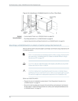
see Installing Adjustable Mounting Brackets in a Rack or Cabinet for a J-EX8200
 |
View all Dell PowerConnect J-8208 manuals
Add to My Manuals
Save this manual to your list of manuals |
Page 124 highlights
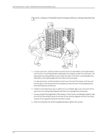
Dell PowerConnect J-Series J-EX8208 Ethernet Switch Hardware Guide CAUTION: Before front-mounting the switch in a rack, have a qualified technician verify that the rack is strong enough to support the switch's weight and is adequately supported at the installation site. Before you install the switch: 1. Prepare the site for installation as described in "Site Preparation Checklist for a J-EX8200 Switch" on page 57. 2. Ensure the site has adequate clearance for both airflow and hardware maintenance as described in "Clearance Requirements for Airflow and Hardware Maintenance for a J-EX8208 Switch" on page 67. 3. Unpack the switch as described in "Unpacking a J-EX8200 Switch" on page 90. 4. Remove all components except the backplane from the chassis. See: • Removing an SRE Module from a J-EX8208 Switch on page 167 • Removing an SF Module from a J-EX8208 Switch on page 169 • Removing a Line Card from a J-EX8200 Switch on page 170 • Removing a Fan Tray from a J-EX8208 Switch on page 163 • Removing an AC Power Supply from a J-EX8200 Switch on page 161 5. In a two-post rack, install the power cord tray at the desired position (see "Installing the Power Cord Tray in a Rack or Cabinet for a J-EX8200 Switch" on page 98). The lip of the power cord tray will support the front of the chassis when you install the switch in the rack. In a four-post rack, install the adjustable mounting brackets at the desired position (see "Installing Adjustable Mounting Brackets in a Rack or Cabinet for a J-EX8200 Switch" on page 95). Optionally, you can also install the power cord tray and use it to manage the power supply cords. 6. Review chassis lifting guidelines as described in "Chassis Lifting Guidelines for J-EX8200 Switches" on page 220. Ensure that you have the following parts and tools available to install the switch: • 24 mounting screws-and 24 cage nuts and washers if your rack requires them-of the appropriate size to secure the chassis to the rack (provided) • A Phillips (+) screwdriver, number 2 or number 3, depending on the size of your rack mounting screws • A flat-blade (-) screwdriver if you are installing the switch in a rack with square, nonthreaded holes 108
-
 1
1 -
2
-
3
-
4
-
5
-
6
-
7
-
8
-
9
-
10
-
11
-
12
-
13
-
14
-
15
-
16
-
17
-
18
-
19
-
20
-
21
-
22
-
23
-
24
-
25
-
26
-
27
-
28
-
29
-
30
-
31
-
32
-
33
-
34
-
35
-
36
-
37
-
38
-
39
-
40
-
41
-
42
-
43
-
44
-
45
-
46
-
47
-
48
-
49
-
50
-
51
-
52
-
53
-
54
-
55
-
56
-
57
-
58
-
59
-
60
-
61
-
62
-
63
-
64
-
65
-
66
-
67
-
68
-
69
-
70
-
71
-
72
-
73
-
74
-
75
-
76
-
77
-
78
-
79
-
80
-
81
-
82
-
83
-
84
-
85
-
86
-
87
-
88
-
89
-
90
-
91
-
92
-
93
-
94
-
95
-
96
-
97
-
98
-
99
-
100
-
101
-
102
-
103
-
104
-
105
-
106
-
107
-
108
-
109
-
110
-
111
-
112
-
113
-
114
-
115
-
116
-
117
-
118
-
 119
119 -
 120
120 -
 121
121 -
 122
122 -
 123
123 -
 124
124 -
 125
125 -
 126
126 -
 127
127 -
 128
128 -
 129
129 -
130
-
131
-
132
-
133
-
134
-
135
-
136
-
137
-
138
-
139
-
140
-
141
-
142
-
143
-
144
-
145
-
146
-
147
-
148
-
149
-
150
-
151
-
152
-
153
-
154
-
155
-
156
-
157
-
158
-
159
-
160
-
161
-
162
-
163
-
164
-
165
-
166
-
167
-
168
-
169
-
170
-
171
-
172
-
173
-
174
-
175
-
176
-
177
-
178
-
179
-
180
-
181
-
182
-
183
-
184
-
185
-
186
-
187
-
188
-
189
-
190
-
191
-
192
-
193
-
194
-
195
-
196
-
197
-
198
-
199
-
200
-
201
-
202
-
203
-
204
-
205
-
206
-
207
-
208
-
209
-
210
-
211
-
212
-
213
-
214
-
215
-
216
-
217
-
218
-
219
-
220
-
221
-
222
-
223
-
224
-
225
-
226
-
227
-
228
-
229
-
230
-
231
-
232
-
233
-
234
-
235
-
236
-
237
-
238
-
239
-
240
-
241
-
242
-
243
-
244
-
245
-
246
-
247
-
248
-
249
-
250
-
251
-
252
-
253
-
254
-
255
-
256
-
257
-
258
-
259
-
260
-
261
-
262
-
263
-
264
-
265
-
266
-
267
-
268
-
269
-
270
-
271
-
272
-
273
-
274
-
275
-
276
 |
 |