Dell PowerConnect J-8208 Hardware Guide - Page 136
Installing an SF Module in a J-EX8208 Switch
 |
View all Dell PowerConnect J-8208 manuals
Add to My Manuals
Save this manual to your list of manuals |
Page 136 highlights
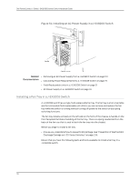
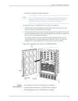
Dell PowerConnect J-Series J-EX8208 Ethernet Switch Hardware Guide Installing an SF Module in a J-EX8208 Switch One SF module is included in the redundant J-EX8208 switch configuration. The SF module can be installed only in the slot labeled SF. The module is keyed so that it does not fit in any other slot in the chassis. NOTE: Do not lift the SF module by holding the ejector levers. The levers cannot support the weight of the module. Lifting the module by the levers might bend the levers. Bent levers prevent the SF module from being properly seated in the chassis. Before you begin installing an SF module in a J-EX8208 switch: • Ensure you understand how to prevent ESD damage. See "Prevention of Electrostatic Discharge Damage on J-EX Series Switches" on page 236. Ensure that you have the following parts and tools available to install an SF module: • Electrostatic discharge (ESD) grounding strap • Phillips (+) screwdriver, number 2 To install an SF module (see Figure 57 on page 121): 1. Attach the electrostatic discharge (ESD) grounding strap to your bare wrist and connect the strap to one of the ESD points on the chassis. 2. If the slot has a cover panel on it, use the Phillips (+) screwdriver, number 2 to remove the two screws on each side of the cover panel. Save the cover panel for later use. 3. Taking care not to touch the leads, pins, or solder connections, pull the SF module out from the bag. 4. Pull both the ejector levers outwards, away from the faceplate of the SF module, until they go no further. 5. Align the sides of the SF module with the guides inside the chassis. 6. Ensuring that the module remains correctly aligned, slide the SF module into the chassis until you feel resistance. 7. Push both the ejector levers towards the faceplate of the SF module until the levers are flush against the faceplate and are fully engaged. 8. Tighten the screws on each side of the SF module by turning them clockwise using the Phillips (+) screwdriver, number 2. Ensure that the SF module is fully seated in the chassis. 9. Verify that the SF module is installed correctly and functioning normally by checking the LEDs on the faceplate of the SF module. The ST LED and SF LED should be lit steady green a few minutes after the SF module is installed. 120
-
 1
1 -
2
-
3
-
4
-
5
-
6
-
7
-
8
-
9
-
10
-
11
-
12
-
13
-
14
-
15
-
16
-
17
-
18
-
19
-
20
-
21
-
22
-
23
-
24
-
25
-
26
-
27
-
28
-
29
-
30
-
31
-
32
-
33
-
34
-
35
-
36
-
37
-
38
-
39
-
40
-
41
-
42
-
43
-
44
-
45
-
46
-
47
-
48
-
49
-
50
-
51
-
52
-
53
-
54
-
55
-
56
-
57
-
58
-
59
-
60
-
61
-
62
-
63
-
64
-
65
-
66
-
67
-
68
-
69
-
70
-
71
-
72
-
73
-
74
-
75
-
76
-
77
-
78
-
79
-
80
-
81
-
82
-
83
-
84
-
85
-
86
-
87
-
88
-
89
-
90
-
91
-
92
-
93
-
94
-
95
-
96
-
97
-
98
-
99
-
100
-
101
-
102
-
103
-
104
-
105
-
106
-
107
-
108
-
109
-
110
-
111
-
112
-
113
-
114
-
115
-
116
-
117
-
118
-
119
-
120
-
121
-
122
-
123
-
124
-
125
-
126
-
127
-
128
-
129
-
130
-
 131
131 -
 132
132 -
 133
133 -
 134
134 -
 135
135 -
 136
136 -
 137
137 -
 138
138 -
 139
139 -
 140
140 -
 141
141 -
142
-
143
-
144
-
145
-
146
-
147
-
148
-
149
-
150
-
151
-
152
-
153
-
154
-
155
-
156
-
157
-
158
-
159
-
160
-
161
-
162
-
163
-
164
-
165
-
166
-
167
-
168
-
169
-
170
-
171
-
172
-
173
-
174
-
175
-
176
-
177
-
178
-
179
-
180
-
181
-
182
-
183
-
184
-
185
-
186
-
187
-
188
-
189
-
190
-
191
-
192
-
193
-
194
-
195
-
196
-
197
-
198
-
199
-
200
-
201
-
202
-
203
-
204
-
205
-
206
-
207
-
208
-
209
-
210
-
211
-
212
-
213
-
214
-
215
-
216
-
217
-
218
-
219
-
220
-
221
-
222
-
223
-
224
-
225
-
226
-
227
-
228
-
229
-
230
-
231
-
232
-
233
-
234
-
235
-
236
-
237
-
238
-
239
-
240
-
241
-
242
-
243
-
244
-
245
-
246
-
247
-
248
-
249
-
250
-
251
-
252
-
253
-
254
-
255
-
256
-
257
-
258
-
259
-
260
-
261
-
262
-
263
-
264
-
265
-
266
-
267
-
268
-
269
-
270
-
271
-
272
-
273
-
274
-
275
-
276
 |
 |
