Dell PowerConnect J-8208 Hardware Guide - Page 70
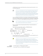
Grounding Cable Lug For a J-EX8208 Switch
 |
View all Dell PowerConnect J-8208 manuals
Add to My Manuals
Save this manual to your list of manuals |
Page 70 highlights
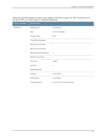
Dell PowerConnect J-Series J-EX8208 Ethernet Switch Hardware Guide J-EX8200 switch, connect a grounding cable to earth ground and then attach it to the chassis grounding points. CAUTION: For installations that require a separate grounding conductor to the chassis, use the protective earthing terminal on the J-EX8200 switch chassis to connect to earth ground. Before switch installation begins, a licensed electrician must attach a cable lug to the grounding cables that you supply. See "Connecting Earth Ground to a J-EX Series Switch" on page 129. A cable with an incorrectly attached lug can damage the switch. A pair of threaded inserts (PEM nuts) is provided on the right side towards the top rear corner of the J-EX8208 chassis for connecting the switch to earth ground. The grounding points fit UNC ¼-20 screws. The grounding points are spaced at 0.625 in. (15.86 mm). NOTE: Grounding is provided to an AC-powered switch when you plug its power supplies into grounded AC power receptacles. Figure 26 on page 54 shows the cable lug that attaches to the grounding cable in a J-EX8208 switch. Figure 26: Grounding Cable Lug For a J-EX8208 Switch The grounding cable that you provide for a J-EX8208 switch must be 6 AWG (13.3 mm2), minimum 60°C wire, or as permitted by the local code. WARNING: The switch is pluggable type A equipment installed in a restricted-access location. It has a separate protective earthing terminal provided on the chassis in addition to the grounding pin of the power supply cord. This separate protective earthing terminal must be permanently connected to earth ground for installations that require a separate grounding conductor to the chassis. Related • AC Power Supply in a J-EX8200 Switch on page 34 Documentation • Connecting AC Power to a J-EX8200 Switch on page 130 54
-
 1
1 -
2
-
3
-
4
-
5
-
6
-
7
-
8
-
9
-
10
-
11
-
12
-
13
-
14
-
15
-
16
-
17
-
18
-
19
-
20
-
21
-
22
-
23
-
24
-
25
-
26
-
27
-
28
-
29
-
30
-
31
-
32
-
33
-
34
-
35
-
36
-
37
-
38
-
39
-
40
-
41
-
42
-
43
-
44
-
45
-
46
-
47
-
48
-
49
-
50
-
51
-
52
-
53
-
54
-
55
-
56
-
57
-
58
-
59
-
60
-
61
-
62
-
63
-
64
-
 65
65 -
 66
66 -
 67
67 -
 68
68 -
 69
69 -
 70
70 -
 71
71 -
 72
72 -
 73
73 -
 74
74 -
 75
75 -
76
-
77
-
78
-
79
-
80
-
81
-
82
-
83
-
84
-
85
-
86
-
87
-
88
-
89
-
90
-
91
-
92
-
93
-
94
-
95
-
96
-
97
-
98
-
99
-
100
-
101
-
102
-
103
-
104
-
105
-
106
-
107
-
108
-
109
-
110
-
111
-
112
-
113
-
114
-
115
-
116
-
117
-
118
-
119
-
120
-
121
-
122
-
123
-
124
-
125
-
126
-
127
-
128
-
129
-
130
-
131
-
132
-
133
-
134
-
135
-
136
-
137
-
138
-
139
-
140
-
141
-
142
-
143
-
144
-
145
-
146
-
147
-
148
-
149
-
150
-
151
-
152
-
153
-
154
-
155
-
156
-
157
-
158
-
159
-
160
-
161
-
162
-
163
-
164
-
165
-
166
-
167
-
168
-
169
-
170
-
171
-
172
-
173
-
174
-
175
-
176
-
177
-
178
-
179
-
180
-
181
-
182
-
183
-
184
-
185
-
186
-
187
-
188
-
189
-
190
-
191
-
192
-
193
-
194
-
195
-
196
-
197
-
198
-
199
-
200
-
201
-
202
-
203
-
204
-
205
-
206
-
207
-
208
-
209
-
210
-
211
-
212
-
213
-
214
-
215
-
216
-
217
-
218
-
219
-
220
-
221
-
222
-
223
-
224
-
225
-
226
-
227
-
228
-
229
-
230
-
231
-
232
-
233
-
234
-
235
-
236
-
237
-
238
-
239
-
240
-
241
-
242
-
243
-
244
-
245
-
246
-
247
-
248
-
249
-
250
-
251
-
252
-
253
-
254
-
255
-
256
-
257
-
258
-
259
-
260
-
261
-
262
-
263
-
264
-
265
-
266
-
267
-
268
-
269
-
270
-
271
-
272
-
273
-
274
-
275
-
276
 |
 |
