Dell PowerConnect J-8208 Hardware Guide - Page 122
Installing a Square-Hole Cage Nut
 |
View all Dell PowerConnect J-8208 manuals
Add to My Manuals
Save this manual to your list of manuals |
Page 122 highlights
g040639 Dell PowerConnect J-Series J-EX8208 Ethernet Switch Hardware Guide Figure 47: Installing a Square-Hole Cage Nut 3. Load the switch onto the lift, making sure it rests securely on the lift platform. Figure 48: Installing the J-EX8208 Switch Chassis Using a Mechanical Lift 4. Using the lift, position the switch in front of the rack or cabinet, centering it in front of the adjustable mounting brackets and/or power cord tray installed in the rack. 5. Lift the chassis approximately 0.75 in. (1.9 cm) above the surface of the adjustable mounting brackets or power cord tray. Position the chassis in the rack as close as possible to resting on the support that the mounting brackets and/or power cord tray provide. 106
-
 1
1 -
2
-
3
-
4
-
5
-
6
-
7
-
8
-
9
-
10
-
11
-
12
-
13
-
14
-
15
-
16
-
17
-
18
-
19
-
20
-
21
-
22
-
23
-
24
-
25
-
26
-
27
-
28
-
29
-
30
-
31
-
32
-
33
-
34
-
35
-
36
-
37
-
38
-
39
-
40
-
41
-
42
-
43
-
44
-
45
-
46
-
47
-
48
-
49
-
50
-
51
-
52
-
53
-
54
-
55
-
56
-
57
-
58
-
59
-
60
-
61
-
62
-
63
-
64
-
65
-
66
-
67
-
68
-
69
-
70
-
71
-
72
-
73
-
74
-
75
-
76
-
77
-
78
-
79
-
80
-
81
-
82
-
83
-
84
-
85
-
86
-
87
-
88
-
89
-
90
-
91
-
92
-
93
-
94
-
95
-
96
-
97
-
98
-
99
-
100
-
101
-
102
-
103
-
104
-
105
-
106
-
107
-
108
-
109
-
110
-
111
-
112
-
113
-
114
-
115
-
116
-
 117
117 -
 118
118 -
 119
119 -
 120
120 -
 121
121 -
 122
122 -
 123
123 -
 124
124 -
 125
125 -
 126
126 -
 127
127 -
128
-
129
-
130
-
131
-
132
-
133
-
134
-
135
-
136
-
137
-
138
-
139
-
140
-
141
-
142
-
143
-
144
-
145
-
146
-
147
-
148
-
149
-
150
-
151
-
152
-
153
-
154
-
155
-
156
-
157
-
158
-
159
-
160
-
161
-
162
-
163
-
164
-
165
-
166
-
167
-
168
-
169
-
170
-
171
-
172
-
173
-
174
-
175
-
176
-
177
-
178
-
179
-
180
-
181
-
182
-
183
-
184
-
185
-
186
-
187
-
188
-
189
-
190
-
191
-
192
-
193
-
194
-
195
-
196
-
197
-
198
-
199
-
200
-
201
-
202
-
203
-
204
-
205
-
206
-
207
-
208
-
209
-
210
-
211
-
212
-
213
-
214
-
215
-
216
-
217
-
218
-
219
-
220
-
221
-
222
-
223
-
224
-
225
-
226
-
227
-
228
-
229
-
230
-
231
-
232
-
233
-
234
-
235
-
236
-
237
-
238
-
239
-
240
-
241
-
242
-
243
-
244
-
245
-
246
-
247
-
248
-
249
-
250
-
251
-
252
-
253
-
254
-
255
-
256
-
257
-
258
-
259
-
260
-
261
-
262
-
263
-
264
-
265
-
266
-
267
-
268
-
269
-
270
-
271
-
272
-
273
-
274
-
275
-
276
 |
 |

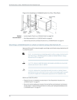
Figure 47: Installing a Square-Hole Cage Nut
g040639
3.
Load the switch onto the lift, making sure it rests securely on the lift platform.
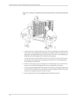
Figure 48: Installing the J-EX8208 Switch Chassis Using a Mechanical
Lift
4.
Using the lift, position the switch in front of the rack or cabinet, centering it in front of
the adjustable mounting brackets and/or power cord tray installed in the rack.
5.
Lift the chassis approximately 0.75 in. (1.9 cm) above the surface of the adjustable
mounting brackets or power cord tray. Position the chassis in the rack as close as
possible to resting on the support that the mounting brackets and/or power cord tray
provide.
106
Dell PowerConnect J-Series J-EX8208 Ethernet Switch Hardware Guide