Dell PowerConnect J-8208 Hardware Guide - Page 84
Airflow Through the J-EX8208 Switch Chassis
 |
View all Dell PowerConnect J-8208 manuals
Add to My Manuals
Save this manual to your list of manuals |
Page 84 highlights
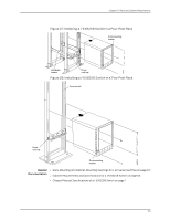
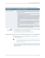
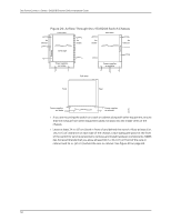
Dell PowerConnect J-Series J-EX8208 Ethernet Switch Hardware Guide Figure 29: Airflow Through the J-EX8208 Switch Chassis • If you are mounting the switch on a rack or cabinet along with other equipment, ensure that the exhaust from other equipment does not blow into the intake vents of the chassis. • Leave at least 24 in. (61 cm) both in front of and behind the switch. Allow at least 6 in. (15.2 cm) of clearance on each side of the chassis. Leave adequate space at the front of the switch for service personnel to remove and install hardware components. NEBS GR-63 recommends that you allow at least 30 in. (76.2 cm) in front of the rack or cabinet and 24 in. (61 cm) behind the rack or cabinet. See Figure 30 on page 69. 68
-
 1
1 -
2
-
3
-
4
-
5
-
6
-
7
-
8
-
9
-
10
-
11
-
12
-
13
-
14
-
15
-
16
-
17
-
18
-
19
-
20
-
21
-
22
-
23
-
24
-
25
-
26
-
27
-
28
-
29
-
30
-
31
-
32
-
33
-
34
-
35
-
36
-
37
-
38
-
39
-
40
-
41
-
42
-
43
-
44
-
45
-
46
-
47
-
48
-
49
-
50
-
51
-
52
-
53
-
54
-
55
-
56
-
57
-
58
-
59
-
60
-
61
-
62
-
63
-
64
-
65
-
66
-
67
-
68
-
69
-
70
-
71
-
72
-
73
-
74
-
75
-
76
-
77
-
78
-
 79
79 -
 80
80 -
 81
81 -
 82
82 -
 83
83 -
 84
84 -
 85
85 -
 86
86 -
 87
87 -
 88
88 -
 89
89 -
90
-
91
-
92
-
93
-
94
-
95
-
96
-
97
-
98
-
99
-
100
-
101
-
102
-
103
-
104
-
105
-
106
-
107
-
108
-
109
-
110
-
111
-
112
-
113
-
114
-
115
-
116
-
117
-
118
-
119
-
120
-
121
-
122
-
123
-
124
-
125
-
126
-
127
-
128
-
129
-
130
-
131
-
132
-
133
-
134
-
135
-
136
-
137
-
138
-
139
-
140
-
141
-
142
-
143
-
144
-
145
-
146
-
147
-
148
-
149
-
150
-
151
-
152
-
153
-
154
-
155
-
156
-
157
-
158
-
159
-
160
-
161
-
162
-
163
-
164
-
165
-
166
-
167
-
168
-
169
-
170
-
171
-
172
-
173
-
174
-
175
-
176
-
177
-
178
-
179
-
180
-
181
-
182
-
183
-
184
-
185
-
186
-
187
-
188
-
189
-
190
-
191
-
192
-
193
-
194
-
195
-
196
-
197
-
198
-
199
-
200
-
201
-
202
-
203
-
204
-
205
-
206
-
207
-
208
-
209
-
210
-
211
-
212
-
213
-
214
-
215
-
216
-
217
-
218
-
219
-
220
-
221
-
222
-
223
-
224
-
225
-
226
-
227
-
228
-
229
-
230
-
231
-
232
-
233
-
234
-
235
-
236
-
237
-
238
-
239
-
240
-
241
-
242
-
243
-
244
-
245
-
246
-
247
-
248
-
249
-
250
-
251
-
252
-
253
-
254
-
255
-
256
-
257
-
258
-
259
-
260
-
261
-
262
-
263
-
264
-
265
-
266
-
267
-
268
-
269
-
270
-
271
-
272
-
273
-
274
-
275
-
276
 |
 |
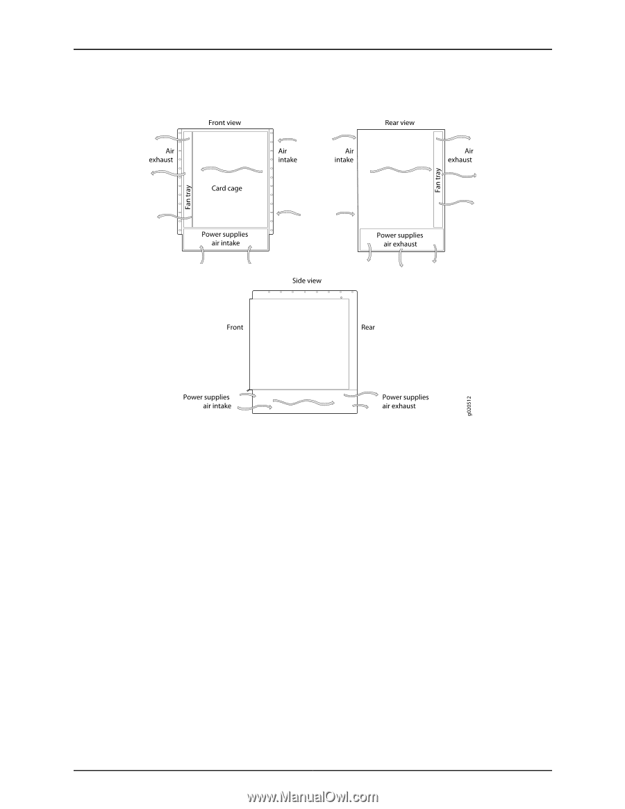
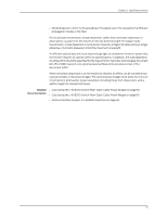
Figure 29: Airflow Through the J-EX8208 Switch Chassis
•
If you are mounting the switch on a rack or cabinet along with other equipment, ensure
that the exhaust from other equipment does not blow into the intake vents of the
chassis.
•
Leave at least 24 in. (61 cm) both in front of and behind the switch. Allow at least 6 in.
(15.2 cm) of clearance on each side of the chassis. Leave adequate space at the front
of the switch for service personnel to remove and install hardware components. NEBS
GR-63 recommends that you allow at least 30 in. (76.2 cm) in front of the rack or
cabinet and 24 in. (61 cm) behind the rack or cabinet. See Figure 30 on page 69.
68
Dell PowerConnect J-Series J-EX8208 Ethernet Switch Hardware Guide