Dell PowerConnect J-8208 Hardware Guide - Page 123
Mounting a J-EX8208 Switch on a Rack or Cabinet Without Using a Mechanical Lift
 |
View all Dell PowerConnect J-8208 manuals
Add to My Manuals
Save this manual to your list of manuals |
Page 123 highlights
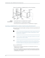
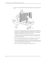
Chapter 8: Installing the Switch 6. In a four-post rack, carefully slide the switch onto the adjustable mounting brackets until the front-mounting brackets ("ears") attached to the chassis contact the rack posts. The adjustable mounting brackets installed in the rack ensure that the holes in the front-mounting brackets align with the holes in the rack posts. In a two-post rack, carefully slide the switch into the rack ensuring that the front bottom of the chassis rests on the lip of the power cord tray. The front-mounting brackets ("ears") prevent the chassis from tipping too far back. 7. Move the lift away from the rack. 8. In a four-post rack, slide the chassis so that the front-mounting bracket is flush with the front of the rack. In a two-post rack, push the bottom of the chassis so that the front-mounting bracket is flush with the front of the rack. 9. Install a mounting screw-plus a washer if you installed cage nuts-into each of the open front-mounting holes aligned with the rack, starting from the bottom. 10. Visually inspect the alignment of the switch. If the switch is installed properly in the rack, all the mounting screws on one side of the rack are aligned with the mounting screws on the opposite side and the switch is level. 11. After ensuring that the switch is aligned properly, tighten the screws. Related • Powering On a J-EX8200 Switch on page 133 Documentation • Connecting and Configuring a J-EX Series Switch (CLI Procedure) on page 144 • Connecting and Configuring a J-EX Series Switch (J-Web Procedure) on page 146 Mounting a J-EX8208 Switch on a Rack or Cabinet Without Using a Mechanical Lift If you cannot use a mechanical lift to install the switch (the preferred method), you can install it manually. CAUTION: The chassis with only the backplane and no other components weighs approximately 89 lb (41 kg). Lifting the chassis and mounting it in a rack or cabinet requires at least three people. The chassis has two handles. Do not lift a fully loaded chassis by the handles; make sure the chassis is empty (contains only the backplane) before you lift it. If two of the people lifting the chassis use the handles to lift it, the third person must lift from the rear of the chassis. The rear of the chassis is heavier than the front of the chassis, so when you lift the chassis by the handles, the chassis tips toward the heavier back end. The person lifting from the back must be aware of this behavior and must be braced to prevent the chassis from tipping over. When lifting the chassis, do not grasp the switch by the blue panel at the top front of the chassis. Doing so can cause the panel to pop off of the switch. 107
-
 1
1 -
2
-
3
-
4
-
5
-
6
-
7
-
8
-
9
-
10
-
11
-
12
-
13
-
14
-
15
-
16
-
17
-
18
-
19
-
20
-
21
-
22
-
23
-
24
-
25
-
26
-
27
-
28
-
29
-
30
-
31
-
32
-
33
-
34
-
35
-
36
-
37
-
38
-
39
-
40
-
41
-
42
-
43
-
44
-
45
-
46
-
47
-
48
-
49
-
50
-
51
-
52
-
53
-
54
-
55
-
56
-
57
-
58
-
59
-
60
-
61
-
62
-
63
-
64
-
65
-
66
-
67
-
68
-
69
-
70
-
71
-
72
-
73
-
74
-
75
-
76
-
77
-
78
-
79
-
80
-
81
-
82
-
83
-
84
-
85
-
86
-
87
-
88
-
89
-
90
-
91
-
92
-
93
-
94
-
95
-
96
-
97
-
98
-
99
-
100
-
101
-
102
-
103
-
104
-
105
-
106
-
107
-
108
-
109
-
110
-
111
-
112
-
113
-
114
-
115
-
116
-
117
-
 118
118 -
 119
119 -
 120
120 -
 121
121 -
 122
122 -
 123
123 -
 124
124 -
 125
125 -
 126
126 -
 127
127 -
 128
128 -
129
-
130
-
131
-
132
-
133
-
134
-
135
-
136
-
137
-
138
-
139
-
140
-
141
-
142
-
143
-
144
-
145
-
146
-
147
-
148
-
149
-
150
-
151
-
152
-
153
-
154
-
155
-
156
-
157
-
158
-
159
-
160
-
161
-
162
-
163
-
164
-
165
-
166
-
167
-
168
-
169
-
170
-
171
-
172
-
173
-
174
-
175
-
176
-
177
-
178
-
179
-
180
-
181
-
182
-
183
-
184
-
185
-
186
-
187
-
188
-
189
-
190
-
191
-
192
-
193
-
194
-
195
-
196
-
197
-
198
-
199
-
200
-
201
-
202
-
203
-
204
-
205
-
206
-
207
-
208
-
209
-
210
-
211
-
212
-
213
-
214
-
215
-
216
-
217
-
218
-
219
-
220
-
221
-
222
-
223
-
224
-
225
-
226
-
227
-
228
-
229
-
230
-
231
-
232
-
233
-
234
-
235
-
236
-
237
-
238
-
239
-
240
-
241
-
242
-
243
-
244
-
245
-
246
-
247
-
248
-
249
-
250
-
251
-
252
-
253
-
254
-
255
-
256
-
257
-
258
-
259
-
260
-
261
-
262
-
263
-
264
-
265
-
266
-
267
-
268
-
269
-
270
-
271
-
272
-
273
-
274
-
275
-
276
 |
 |
