Dell PowerConnect J-8208 Hardware Guide - Page 118
Installing a Round-Hole Cage Nut Clip Nut
 |
View all Dell PowerConnect J-8208 manuals
Add to My Manuals
Save this manual to your list of manuals |
Page 118 highlights
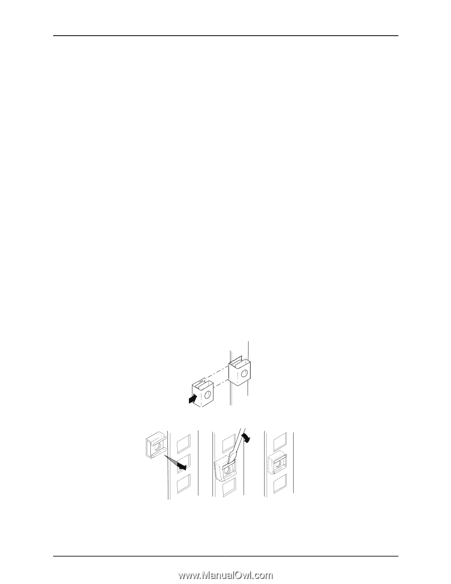
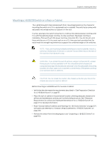
Dell PowerConnect J-Series J-EX8208 Ethernet Switch Hardware Guide Ensure that you have the following parts and tools available to mount the switch on a rack or cabinet: • A Phillips (+) screwdriver, number 2 or number 3, depending on the size of your rack mounting screws, for mounting the switch on a rack or cabinet • A Phillips (+) screwdriver, number 1, to remove the power supplies from the chassis if you are mounting the switch without using a mechanical lift • A flat-blade (-) screwdriver if you are installing the switch in a rack with square, nonthreaded holes • 24 mounting screws-and 24 cage nuts and washers if your rack requires them-of the appropriate size to secure the chassis to the rack (provided) To mount the J-EX8208 switch on a rack or cabinet (see Figure 44 on page 103 and Figure 45 on page 104): 1. In a four-post rack or cabinet, install the adjustable mounting brackets at the desired position (see "Installing Adjustable Mounting Brackets in a Rack or Cabinet for a J-EX8200 Switch" on page 95). In a two-post rack or cabinet, install the power cord tray (see "Installing the Power Cord Tray in a Rack or Cabinet for a J-EX8200 Switch" on page 98). The power cord tray is optional for four-post rack installation. 2. If your rack has unthreaded round or square holes, install 24 cage nuts in the appropriate holes on the left front and right front rack posts, making sure that the 12 cage nuts on each post are on the same rack level front and back. Use Figure 42 on page 102 or Figure 43 on page 102 to help you with cage-nut installation. Figure 42: Installing a Round-Hole Cage Nut (Clip Nut) Figure 43: Installing a Square-Hole Cage Nut 102 g040637 g040639
-
 1
1 -
2
-
3
-
4
-
5
-
6
-
7
-
8
-
9
-
10
-
11
-
12
-
13
-
14
-
15
-
16
-
17
-
18
-
19
-
20
-
21
-
22
-
23
-
24
-
25
-
26
-
27
-
28
-
29
-
30
-
31
-
32
-
33
-
34
-
35
-
36
-
37
-
38
-
39
-
40
-
41
-
42
-
43
-
44
-
45
-
46
-
47
-
48
-
49
-
50
-
51
-
52
-
53
-
54
-
55
-
56
-
57
-
58
-
59
-
60
-
61
-
62
-
63
-
64
-
65
-
66
-
67
-
68
-
69
-
70
-
71
-
72
-
73
-
74
-
75
-
76
-
77
-
78
-
79
-
80
-
81
-
82
-
83
-
84
-
85
-
86
-
87
-
88
-
89
-
90
-
91
-
92
-
93
-
94
-
95
-
96
-
97
-
98
-
99
-
100
-
101
-
102
-
103
-
104
-
105
-
106
-
107
-
108
-
109
-
110
-
111
-
112
-
 113
113 -
 114
114 -
 115
115 -
 116
116 -
 117
117 -
 118
118 -
 119
119 -
 120
120 -
 121
121 -
 122
122 -
 123
123 -
124
-
125
-
126
-
127
-
128
-
129
-
130
-
131
-
132
-
133
-
134
-
135
-
136
-
137
-
138
-
139
-
140
-
141
-
142
-
143
-
144
-
145
-
146
-
147
-
148
-
149
-
150
-
151
-
152
-
153
-
154
-
155
-
156
-
157
-
158
-
159
-
160
-
161
-
162
-
163
-
164
-
165
-
166
-
167
-
168
-
169
-
170
-
171
-
172
-
173
-
174
-
175
-
176
-
177
-
178
-
179
-
180
-
181
-
182
-
183
-
184
-
185
-
186
-
187
-
188
-
189
-
190
-
191
-
192
-
193
-
194
-
195
-
196
-
197
-
198
-
199
-
200
-
201
-
202
-
203
-
204
-
205
-
206
-
207
-
208
-
209
-
210
-
211
-
212
-
213
-
214
-
215
-
216
-
217
-
218
-
219
-
220
-
221
-
222
-
223
-
224
-
225
-
226
-
227
-
228
-
229
-
230
-
231
-
232
-
233
-
234
-
235
-
236
-
237
-
238
-
239
-
240
-
241
-
242
-
243
-
244
-
245
-
246
-
247
-
248
-
249
-
250
-
251
-
252
-
253
-
254
-
255
-
256
-
257
-
258
-
259
-
260
-
261
-
262
-
263
-
264
-
265
-
266
-
267
-
268
-
269
-
270
-
271
-
272
-
273
-
274
-
275
-
276
 |
 |