Dell PowerConnect J-8208 Hardware Guide - Page 117
Mounting a J-EX8208 Switch on a Rack or Cabinet
 |
View all Dell PowerConnect J-8208 manuals
Add to My Manuals
Save this manual to your list of manuals |
Page 117 highlights
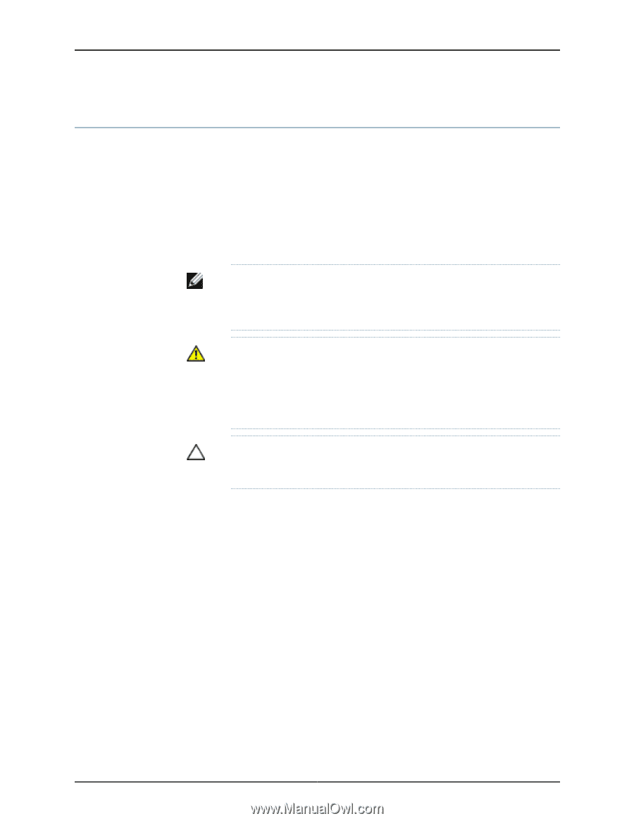
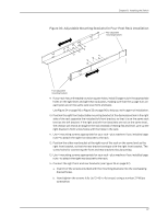
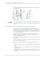
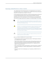
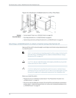
Chapter 8: Installing the Switch Mounting a J-EX8208 Switch on a Rack or Cabinet The J-EX8208 switch ships installed with front-mounting brackets on the chassis for mounting the switch on a 19-in. equipment rack or cabinet. The switch also comes with adjustable mounting brackets to support it in the rack. In a four-post rack, the switch consumes 14 U without the optional power cord tray and 15 U with the optional power cord tray. In a two-post rack, the power cord tray is mandatory. The switch with the power cord tray consumes 15 U. You can mount up to three switches on a 42 U four-post rack or on a 45 U two-post rack provided that the racks meet the strength requirements to support the combined weight of the switches. NOTE: If you are mounting multiple switches on a rack or cabinet, mount a switch on the bottom of the rack or cabinet first and then mount the rest of the switches from bottom to top. WARNING: If you install the switch without using a mechanical lift, at least three people must be available to lift the unloaded switch chassis (all components except the backplane removed) onto the adjustable mounting brackets (in a four-post rack or cabinet) or onto the lip of the power cord tray (in a two-post rack or cabinet). CAUTION: Do not install line cards in the chassis until after you mount the chassis securely on a rack or cabinet. Before mounting a J-EX8208 switch on a rack or cabinet: • Verify that the site meets the requirements described in "Site Preparation Checklist for a J-EX8200 Switch" on page 57. • Place the rack or cabinet in its permanent location, allowing adequate clearance for airflow and maintenance, and secure it to the building structure. See "Clearance Requirements for Airflow and Hardware Maintenance for a J-EX8208 Switch" on page 67 for detailed information. • Read "General Safety Guidelines and Warnings for J-EX Series Switches" on page 207, with particular attention to "Chassis Lifting Guidelines for J-EX8200 Switches" on page 220. • Remove the switch from the shipping box (see "Unpacking a J-EX8200 Switch" on page 90). 101
-
 1
1 -
2
-
3
-
4
-
5
-
6
-
7
-
8
-
9
-
10
-
11
-
12
-
13
-
14
-
15
-
16
-
17
-
18
-
19
-
20
-
21
-
22
-
23
-
24
-
25
-
26
-
27
-
28
-
29
-
30
-
31
-
32
-
33
-
34
-
35
-
36
-
37
-
38
-
39
-
40
-
41
-
42
-
43
-
44
-
45
-
46
-
47
-
48
-
49
-
50
-
51
-
52
-
53
-
54
-
55
-
56
-
57
-
58
-
59
-
60
-
61
-
62
-
63
-
64
-
65
-
66
-
67
-
68
-
69
-
70
-
71
-
72
-
73
-
74
-
75
-
76
-
77
-
78
-
79
-
80
-
81
-
82
-
83
-
84
-
85
-
86
-
87
-
88
-
89
-
90
-
91
-
92
-
93
-
94
-
95
-
96
-
97
-
98
-
99
-
100
-
101
-
102
-
103
-
104
-
105
-
106
-
107
-
108
-
109
-
110
-
111
-
 112
112 -
 113
113 -
 114
114 -
 115
115 -
 116
116 -
 117
117 -
 118
118 -
 119
119 -
 120
120 -
 121
121 -
 122
122 -
123
-
124
-
125
-
126
-
127
-
128
-
129
-
130
-
131
-
132
-
133
-
134
-
135
-
136
-
137
-
138
-
139
-
140
-
141
-
142
-
143
-
144
-
145
-
146
-
147
-
148
-
149
-
150
-
151
-
152
-
153
-
154
-
155
-
156
-
157
-
158
-
159
-
160
-
161
-
162
-
163
-
164
-
165
-
166
-
167
-
168
-
169
-
170
-
171
-
172
-
173
-
174
-
175
-
176
-
177
-
178
-
179
-
180
-
181
-
182
-
183
-
184
-
185
-
186
-
187
-
188
-
189
-
190
-
191
-
192
-
193
-
194
-
195
-
196
-
197
-
198
-
199
-
200
-
201
-
202
-
203
-
204
-
205
-
206
-
207
-
208
-
209
-
210
-
211
-
212
-
213
-
214
-
215
-
216
-
217
-
218
-
219
-
220
-
221
-
222
-
223
-
224
-
225
-
226
-
227
-
228
-
229
-
230
-
231
-
232
-
233
-
234
-
235
-
236
-
237
-
238
-
239
-
240
-
241
-
242
-
243
-
244
-
245
-
246
-
247
-
248
-
249
-
250
-
251
-
252
-
253
-
254
-
255
-
256
-
257
-
258
-
259
-
260
-
261
-
262
-
263
-
264
-
265
-
266
-
267
-
268
-
269
-
270
-
271
-
272
-
273
-
274
-
275
-
276
 |
 |