Dell PowerConnect J-8208 Hardware Guide - Page 60
Management Port Connector Pinout Information for a J-EX8200 Switch
 |
View all Dell PowerConnect J-8208 manuals
Add to My Manuals
Save this manual to your list of manuals |
Page 60 highlights
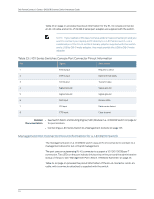
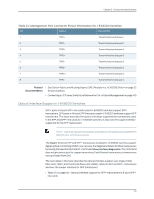
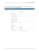
Dell PowerConnect J-Series J-EX8208 Ethernet Switch Hardware Guide Table 23 on page 44 provides the pinout information for the RJ-45 console connector. An RJ-45 cable and an RJ-45 to DB-9 serial port adapter are supplied with the switch. NOTE: If your laptop or PC does not have a DB-9 male connector pin and you want to connect your laptop or PC directly to a J-EX Series switch, use a combination of the RJ-45 to DB-9 female adapter supplied with the switch and a USB to DB-9 male adapter. You must provide the USB to DB-9 male adapter. Table 23: J-EX Series Switches Console Port Connector Pinout Information Pin Signal Description 1 RTS Output Request to send 2 DTR Output Data terminal ready 3 TxD Output Transmit data 4 Signal Ground Signal ground 5 Signal Ground Signal ground 6 RxD Input Receive data 7 CD Input Data carrier detect 8 CTS Input Clear to send Related • See Switch Fabric and Routing Engine (SRE) Module in a J-EX8208 Switch on page 22 Documentation for port location. • Connecting a J-EX Series Switch to a Management Console on page 135 Management Port Connector Pinout Information for a J-EX8200 Switch The management port on a J-EX8200 switch uses an RJ-45 connector to connect to a management device for out-of-band management. The port uses an autosensing RJ-45 connector to support a 10/100/1000Base-T connection. Two LEDs on the port indicate link/activity on the port and the administrative status of the port. See "Management Port LEDs in J-EX8200 Switches" on page 25. Table 24 on page 45 provides the pinout information of the RJ-45 connector. An RJ-45 cable, with a connector attached, is supplied with the switch. 44
-
 1
1 -
2
-
3
-
4
-
5
-
6
-
7
-
8
-
9
-
10
-
11
-
12
-
13
-
14
-
15
-
16
-
17
-
18
-
19
-
20
-
21
-
22
-
23
-
24
-
25
-
26
-
27
-
28
-
29
-
30
-
31
-
32
-
33
-
34
-
35
-
36
-
37
-
38
-
39
-
40
-
41
-
42
-
43
-
44
-
45
-
46
-
47
-
48
-
49
-
50
-
51
-
52
-
53
-
54
-
 55
55 -
 56
56 -
 57
57 -
 58
58 -
 59
59 -
 60
60 -
 61
61 -
 62
62 -
 63
63 -
 64
64 -
 65
65 -
66
-
67
-
68
-
69
-
70
-
71
-
72
-
73
-
74
-
75
-
76
-
77
-
78
-
79
-
80
-
81
-
82
-
83
-
84
-
85
-
86
-
87
-
88
-
89
-
90
-
91
-
92
-
93
-
94
-
95
-
96
-
97
-
98
-
99
-
100
-
101
-
102
-
103
-
104
-
105
-
106
-
107
-
108
-
109
-
110
-
111
-
112
-
113
-
114
-
115
-
116
-
117
-
118
-
119
-
120
-
121
-
122
-
123
-
124
-
125
-
126
-
127
-
128
-
129
-
130
-
131
-
132
-
133
-
134
-
135
-
136
-
137
-
138
-
139
-
140
-
141
-
142
-
143
-
144
-
145
-
146
-
147
-
148
-
149
-
150
-
151
-
152
-
153
-
154
-
155
-
156
-
157
-
158
-
159
-
160
-
161
-
162
-
163
-
164
-
165
-
166
-
167
-
168
-
169
-
170
-
171
-
172
-
173
-
174
-
175
-
176
-
177
-
178
-
179
-
180
-
181
-
182
-
183
-
184
-
185
-
186
-
187
-
188
-
189
-
190
-
191
-
192
-
193
-
194
-
195
-
196
-
197
-
198
-
199
-
200
-
201
-
202
-
203
-
204
-
205
-
206
-
207
-
208
-
209
-
210
-
211
-
212
-
213
-
214
-
215
-
216
-
217
-
218
-
219
-
220
-
221
-
222
-
223
-
224
-
225
-
226
-
227
-
228
-
229
-
230
-
231
-
232
-
233
-
234
-
235
-
236
-
237
-
238
-
239
-
240
-
241
-
242
-
243
-
244
-
245
-
246
-
247
-
248
-
249
-
250
-
251
-
252
-
253
-
254
-
255
-
256
-
257
-
258
-
259
-
260
-
261
-
262
-
263
-
264
-
265
-
266
-
267
-
268
-
269
-
270
-
271
-
272
-
273
-
274
-
275
-
276
 |
 |
