Dell PowerConnect J-8208 Hardware Guide - Page 156
Connecting a J-EX Series Switch to a Network for Out-of-Band Management
 |
View all Dell PowerConnect J-8208 manuals
Add to My Manuals
Save this manual to your list of manuals |
Page 156 highlights
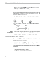
Dell PowerConnect J-Series J-EX8208 Ethernet Switch Hardware Guide 7. Connect one end of the phone cable to the modem and the other end to your telephone network. 8. Turn on the power to your modem. 9. Power on the switch. Related • Connecting a J-EX Series Switch to a Management Console on page 135 Documentation • Console Port Connector Pinout Information for a J-EX Series Switch on page 43 Connecting a J-EX Series Switch to a Network for Out-of-Band Management You can monitor and manage a J-EX Series switch using a dedicated management channel. J-EX Series switches have a management port with an RJ-45 connector for out-of-band management. Use the management port to connect the J-EX Series switch to the management device. Ensure that you have an Ethernet cable with an RJ-45 connector available. One such cable is provided with the switch. Figure 71 on page 140 shows the RJ-45 connector of the Ethernet cable supplied with the switch. Figure 71: Ethernet Cable Connector To connect a J-EX Series switch to a network for out-of-band management (see Figure 72 on page 141): 1. Connect one end of the Ethernet cable to the management port (labeled MGMT) on the J-EX Series switch. For the location of the MGMT port, see "Switch Fabric and Routing Engine (SRE) Module in a J-EX8208 Switch" on page 22. 2. Connect the other end of the Ethernet cable to the management device. 140
-
 1
1 -
2
-
3
-
4
-
5
-
6
-
7
-
8
-
9
-
10
-
11
-
12
-
13
-
14
-
15
-
16
-
17
-
18
-
19
-
20
-
21
-
22
-
23
-
24
-
25
-
26
-
27
-
28
-
29
-
30
-
31
-
32
-
33
-
34
-
35
-
36
-
37
-
38
-
39
-
40
-
41
-
42
-
43
-
44
-
45
-
46
-
47
-
48
-
49
-
50
-
51
-
52
-
53
-
54
-
55
-
56
-
57
-
58
-
59
-
60
-
61
-
62
-
63
-
64
-
65
-
66
-
67
-
68
-
69
-
70
-
71
-
72
-
73
-
74
-
75
-
76
-
77
-
78
-
79
-
80
-
81
-
82
-
83
-
84
-
85
-
86
-
87
-
88
-
89
-
90
-
91
-
92
-
93
-
94
-
95
-
96
-
97
-
98
-
99
-
100
-
101
-
102
-
103
-
104
-
105
-
106
-
107
-
108
-
109
-
110
-
111
-
112
-
113
-
114
-
115
-
116
-
117
-
118
-
119
-
120
-
121
-
122
-
123
-
124
-
125
-
126
-
127
-
128
-
129
-
130
-
131
-
132
-
133
-
134
-
135
-
136
-
137
-
138
-
139
-
140
-
141
-
142
-
143
-
144
-
145
-
146
-
147
-
148
-
149
-
150
-
 151
151 -
 152
152 -
 153
153 -
 154
154 -
 155
155 -
 156
156 -
 157
157 -
 158
158 -
 159
159 -
 160
160 -
 161
161 -
162
-
163
-
164
-
165
-
166
-
167
-
168
-
169
-
170
-
171
-
172
-
173
-
174
-
175
-
176
-
177
-
178
-
179
-
180
-
181
-
182
-
183
-
184
-
185
-
186
-
187
-
188
-
189
-
190
-
191
-
192
-
193
-
194
-
195
-
196
-
197
-
198
-
199
-
200
-
201
-
202
-
203
-
204
-
205
-
206
-
207
-
208
-
209
-
210
-
211
-
212
-
213
-
214
-
215
-
216
-
217
-
218
-
219
-
220
-
221
-
222
-
223
-
224
-
225
-
226
-
227
-
228
-
229
-
230
-
231
-
232
-
233
-
234
-
235
-
236
-
237
-
238
-
239
-
240
-
241
-
242
-
243
-
244
-
245
-
246
-
247
-
248
-
249
-
250
-
251
-
252
-
253
-
254
-
255
-
256
-
257
-
258
-
259
-
260
-
261
-
262
-
263
-
264
-
265
-
266
-
267
-
268
-
269
-
270
-
271
-
272
-
273
-
274
-
275
-
276
 |
 |
