Dell PowerConnect J-8208 Hardware Guide - Page 152
Connecting a J-EX Series Switch to a Modem
 |
View all Dell PowerConnect J-8208 manuals
Add to My Manuals
Save this manual to your list of manuals |
Page 152 highlights
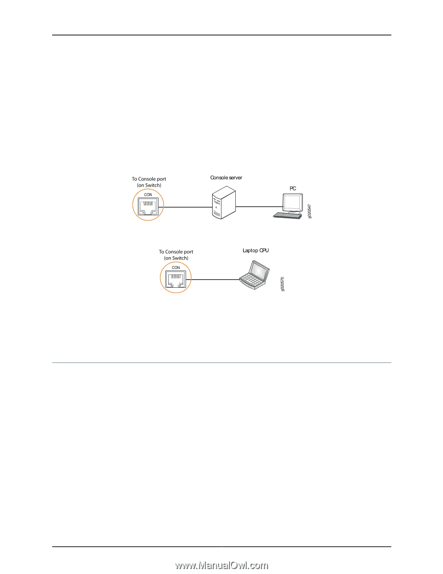
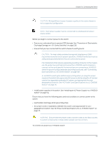
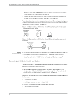
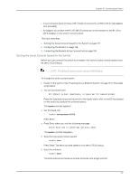
Dell PowerConnect J-Series J-EX8208 Ethernet Switch Hardware Guide For the location of the CON/CONSOLE port, see "Switch Fabric and Routing Engine (SRE) Module in a J-EX8208 Switch" on page 22. 2. Connect the other end of the Ethernet cable into the console server (see Figure 68 on page 136) or management console (see Figure 69 on page 136). To configure the switch from the management console, see"Connecting and Configuring a J-EX Series Switch (CLI Procedure)" on page 144 or "Connecting and Configuring a J-EX Series Switch (J-Web Procedure)" on page 146. Figure 68: Connecting a J-EX Series Switch to a Management Console Through a Console Server Figure 69: Connecting a J-EX Series Switch Directly to a Management Console Related • Connecting a J-EX Series Switch to a Network for Out-of-Band Management on page 140 Documentation • Console Port Connector Pinout Information for a J-EX Series Switch on page 43 • Cables Connecting the J-EX8200 Switch to Management Devices on page 71 Connecting a J-EX Series Switch to a Modem You can connect a J-EX Series switch to a modem through the console port on the switch. Before you connect the switch to a modem: • Perform the initial setup and configuration of the switch. See "Connecting and Configuring a J-EX Series Switch (CLI Procedure)" on page 144 or "Connecting and Configuring a J-EX Series Switch (J-Web Procedure)" on page 146. Ensure that you have the following parts available before you begin to connect the switch to the modem: • A modem (not provided) • A desktop or notebook computer (not provided) • An RJ-45 to DB-9 adapter and an Ethernet cable (provided) • A phone cable (not provided) 136
-
 1
1 -
2
-
3
-
4
-
5
-
6
-
7
-
8
-
9
-
10
-
11
-
12
-
13
-
14
-
15
-
16
-
17
-
18
-
19
-
20
-
21
-
22
-
23
-
24
-
25
-
26
-
27
-
28
-
29
-
30
-
31
-
32
-
33
-
34
-
35
-
36
-
37
-
38
-
39
-
40
-
41
-
42
-
43
-
44
-
45
-
46
-
47
-
48
-
49
-
50
-
51
-
52
-
53
-
54
-
55
-
56
-
57
-
58
-
59
-
60
-
61
-
62
-
63
-
64
-
65
-
66
-
67
-
68
-
69
-
70
-
71
-
72
-
73
-
74
-
75
-
76
-
77
-
78
-
79
-
80
-
81
-
82
-
83
-
84
-
85
-
86
-
87
-
88
-
89
-
90
-
91
-
92
-
93
-
94
-
95
-
96
-
97
-
98
-
99
-
100
-
101
-
102
-
103
-
104
-
105
-
106
-
107
-
108
-
109
-
110
-
111
-
112
-
113
-
114
-
115
-
116
-
117
-
118
-
119
-
120
-
121
-
122
-
123
-
124
-
125
-
126
-
127
-
128
-
129
-
130
-
131
-
132
-
133
-
134
-
135
-
136
-
137
-
138
-
139
-
140
-
141
-
142
-
143
-
144
-
145
-
146
-
 147
147 -
 148
148 -
 149
149 -
 150
150 -
 151
151 -
 152
152 -
 153
153 -
 154
154 -
 155
155 -
 156
156 -
 157
157 -
158
-
159
-
160
-
161
-
162
-
163
-
164
-
165
-
166
-
167
-
168
-
169
-
170
-
171
-
172
-
173
-
174
-
175
-
176
-
177
-
178
-
179
-
180
-
181
-
182
-
183
-
184
-
185
-
186
-
187
-
188
-
189
-
190
-
191
-
192
-
193
-
194
-
195
-
196
-
197
-
198
-
199
-
200
-
201
-
202
-
203
-
204
-
205
-
206
-
207
-
208
-
209
-
210
-
211
-
212
-
213
-
214
-
215
-
216
-
217
-
218
-
219
-
220
-
221
-
222
-
223
-
224
-
225
-
226
-
227
-
228
-
229
-
230
-
231
-
232
-
233
-
234
-
235
-
236
-
237
-
238
-
239
-
240
-
241
-
242
-
243
-
244
-
245
-
246
-
247
-
248
-
249
-
250
-
251
-
252
-
253
-
254
-
255
-
256
-
257
-
258
-
259
-
260
-
261
-
262
-
263
-
264
-
265
-
266
-
267
-
268
-
269
-
270
-
271
-
272
-
273
-
274
-
275
-
276
 |
 |