Dell PowerConnect J-8208 Hardware Guide - Page 83
Clearance Requirements for Airflow and Hardware Maintenance for a J-EX8208 Switch
 |
View all Dell PowerConnect J-8208 manuals
Add to My Manuals
Save this manual to your list of manuals |
Page 83 highlights
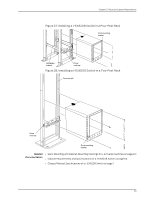
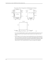
Chapter 5: Rack and Cabinet Requirements Table 31: Cabinet Requirements and Specifications for a J-EX8208 Switch (continued) Cabinet Requirement Guidelines for the J-EX8208 Switch Cabinet airflow requirements When you mount the switch on a cabinet, ensure that ventilation through the cabinet is sufficient to prevent overheating. Consider the following requirements list when planning for chassis cooling: • Ensure that the cool air supply you provide through the cabinet adequately dissipates the thermal output of the switch (or switches). • Ensure that the cabinet allows the chassis hot exhaust air to exit the cabinet without recirculating into the switch. An open cabinet (without a top or doors) that employs hot air exhaust extraction from the top allows the best airflow through the chassis. If the cabinet contains a top or doors, perforations in these elements assist with removing the hot air exhaust. For an illustration of chassis airflow, see "Clearance Requirements for Airflow and Hardware Maintenance for a J-EX8208 Switch" on page 67. • The switch fans exhaust hot air through the right side of the chassis (the left side when you face the front of the chassis, where the fan tray slides in). Install the switch in the cabinet in a way that maximizes the open space on the fan tray side of the chassis. This maximizes the clearance for critical airflow. • Route and dress all cables to minimize the blockage of airflow to and from the chassis. • Ensure that the spacing of rails and adjacent racks allows for the proper clearance around the switch and rack as specified in "Clearance Requirements for Airflow and Hardware Maintenance for a J-EX8208 Switch" on page 67. Related • Rack-Mounting and Cabinet-Mounting Warnings for J-EX Series Switches on page 221 Documentation • Rack Requirements for a J-EX8208 Switch on page 63 • Chassis Physical Specifications of a J-EX8208 Switch on page 7 Clearance Requirements for Airflow and Hardware Maintenance for a J-EX8208 Switch When planning the site for installing a J-EX8208 switch, you must allow sufficient clearance around the switch. NOTE: To manage airflow in a hot-aisle--cold-aisle data center setup, you might want to use the customized rack solution for J-EX8200 switches offered by Chatsworth Products, Inc. • Allow at least 6 in. (15.2 cm) of clearance on each side of the chassis. For the cooling system to function properly, the airflow around the chassis must be unrestricted. See Figure 29 on page 68. 67
-
 1
1 -
2
-
3
-
4
-
5
-
6
-
7
-
8
-
9
-
10
-
11
-
12
-
13
-
14
-
15
-
16
-
17
-
18
-
19
-
20
-
21
-
22
-
23
-
24
-
25
-
26
-
27
-
28
-
29
-
30
-
31
-
32
-
33
-
34
-
35
-
36
-
37
-
38
-
39
-
40
-
41
-
42
-
43
-
44
-
45
-
46
-
47
-
48
-
49
-
50
-
51
-
52
-
53
-
54
-
55
-
56
-
57
-
58
-
59
-
60
-
61
-
62
-
63
-
64
-
65
-
66
-
67
-
68
-
69
-
70
-
71
-
72
-
73
-
74
-
75
-
76
-
77
-
 78
78 -
 79
79 -
 80
80 -
 81
81 -
 82
82 -
 83
83 -
 84
84 -
 85
85 -
 86
86 -
 87
87 -
 88
88 -
89
-
90
-
91
-
92
-
93
-
94
-
95
-
96
-
97
-
98
-
99
-
100
-
101
-
102
-
103
-
104
-
105
-
106
-
107
-
108
-
109
-
110
-
111
-
112
-
113
-
114
-
115
-
116
-
117
-
118
-
119
-
120
-
121
-
122
-
123
-
124
-
125
-
126
-
127
-
128
-
129
-
130
-
131
-
132
-
133
-
134
-
135
-
136
-
137
-
138
-
139
-
140
-
141
-
142
-
143
-
144
-
145
-
146
-
147
-
148
-
149
-
150
-
151
-
152
-
153
-
154
-
155
-
156
-
157
-
158
-
159
-
160
-
161
-
162
-
163
-
164
-
165
-
166
-
167
-
168
-
169
-
170
-
171
-
172
-
173
-
174
-
175
-
176
-
177
-
178
-
179
-
180
-
181
-
182
-
183
-
184
-
185
-
186
-
187
-
188
-
189
-
190
-
191
-
192
-
193
-
194
-
195
-
196
-
197
-
198
-
199
-
200
-
201
-
202
-
203
-
204
-
205
-
206
-
207
-
208
-
209
-
210
-
211
-
212
-
213
-
214
-
215
-
216
-
217
-
218
-
219
-
220
-
221
-
222
-
223
-
224
-
225
-
226
-
227
-
228
-
229
-
230
-
231
-
232
-
233
-
234
-
235
-
236
-
237
-
238
-
239
-
240
-
241
-
242
-
243
-
244
-
245
-
246
-
247
-
248
-
249
-
250
-
251
-
252
-
253
-
254
-
255
-
256
-
257
-
258
-
259
-
260
-
261
-
262
-
263
-
264
-
265
-
266
-
267
-
268
-
269
-
270
-
271
-
272
-
273
-
274
-
275
-
276
 |
 |
