Dell PowerConnect J-8208 Hardware Guide - Page 135
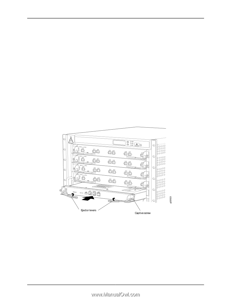
Installing an SRE Module in a J-EX8208 Switch
 |
View all Dell PowerConnect J-8208 manuals
Add to My Manuals
Save this manual to your list of manuals |
Page 135 highlights
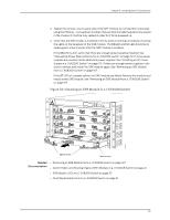
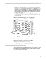
Chapter 9: Installing Switch Components 8. Tighten the screws, one on each side of the SRE module, by turning them clockwise using the Phillips (+) screwdriver, number 2. Ensure that the SRE module is fully seated in the chassis. It must be fully seated in order for it to be powered up. 9. Verify that the SRE module is installed correctly and functioning normally by checking the LEDs on the faceplate of the SRE module. The ON LED and ST LED should be lit steady green a few minutes after the SRE module is installed. If the ON LED is unlit, verify that there are enough power supplies installed. See "Calculating Power Requirements for a J-EX8208 Switch" on page 79. If more power supplies are needed, install additional power supplies. See "Installing an AC Power Supply in a J-EX8200 Switch" on page 114. If there are enough power supplies in the switch, remove and install the SRE module again. See "Removing an SRE Module from a J-EX8208 Switch" on page 167. If the ST LED is lit steady yellow, the SRE module has failed. Remove the module and install a new SRE module. See "Removing an SRE Module from a J-EX8208 Switch" on page 167. Figure 56: Installing an SRE Module in a J-EX8208 Switch Related • Removing an SRE Module from a J-EX8208 Switch on page 167 Documentation • Switch Fabric and Routing Engine (SRE) Module in a J-EX8208 Switch on page 22 • SRE Module LEDs in a J-EX8208 Switch on page 23 • Field-Replaceable Units in a J-EX8208 Switch on page 21 119
-
 1
1 -
2
-
3
-
4
-
5
-
6
-
7
-
8
-
9
-
10
-
11
-
12
-
13
-
14
-
15
-
16
-
17
-
18
-
19
-
20
-
21
-
22
-
23
-
24
-
25
-
26
-
27
-
28
-
29
-
30
-
31
-
32
-
33
-
34
-
35
-
36
-
37
-
38
-
39
-
40
-
41
-
42
-
43
-
44
-
45
-
46
-
47
-
48
-
49
-
50
-
51
-
52
-
53
-
54
-
55
-
56
-
57
-
58
-
59
-
60
-
61
-
62
-
63
-
64
-
65
-
66
-
67
-
68
-
69
-
70
-
71
-
72
-
73
-
74
-
75
-
76
-
77
-
78
-
79
-
80
-
81
-
82
-
83
-
84
-
85
-
86
-
87
-
88
-
89
-
90
-
91
-
92
-
93
-
94
-
95
-
96
-
97
-
98
-
99
-
100
-
101
-
102
-
103
-
104
-
105
-
106
-
107
-
108
-
109
-
110
-
111
-
112
-
113
-
114
-
115
-
116
-
117
-
118
-
119
-
120
-
121
-
122
-
123
-
124
-
125
-
126
-
127
-
128
-
129
-
 130
130 -
 131
131 -
 132
132 -
 133
133 -
 134
134 -
 135
135 -
 136
136 -
 137
137 -
 138
138 -
 139
139 -
 140
140 -
141
-
142
-
143
-
144
-
145
-
146
-
147
-
148
-
149
-
150
-
151
-
152
-
153
-
154
-
155
-
156
-
157
-
158
-
159
-
160
-
161
-
162
-
163
-
164
-
165
-
166
-
167
-
168
-
169
-
170
-
171
-
172
-
173
-
174
-
175
-
176
-
177
-
178
-
179
-
180
-
181
-
182
-
183
-
184
-
185
-
186
-
187
-
188
-
189
-
190
-
191
-
192
-
193
-
194
-
195
-
196
-
197
-
198
-
199
-
200
-
201
-
202
-
203
-
204
-
205
-
206
-
207
-
208
-
209
-
210
-
211
-
212
-
213
-
214
-
215
-
216
-
217
-
218
-
219
-
220
-
221
-
222
-
223
-
224
-
225
-
226
-
227
-
228
-
229
-
230
-
231
-
232
-
233
-
234
-
235
-
236
-
237
-
238
-
239
-
240
-
241
-
242
-
243
-
244
-
245
-
246
-
247
-
248
-
249
-
250
-
251
-
252
-
253
-
254
-
255
-
256
-
257
-
258
-
259
-
260
-
261
-
262
-
263
-
264
-
265
-
266
-
267
-
268
-
269
-
270
-
271
-
272
-
273
-
274
-
275
-
276
 |
 |