Dell PowerConnect J-8208 Hardware Guide - Page 110
Table 41: Accessory Box Parts List, Unpacking a J-EX8200 Switch
 |
View all Dell PowerConnect J-8208 manuals
Add to My Manuals
Save this manual to your list of manuals |
Page 110 highlights
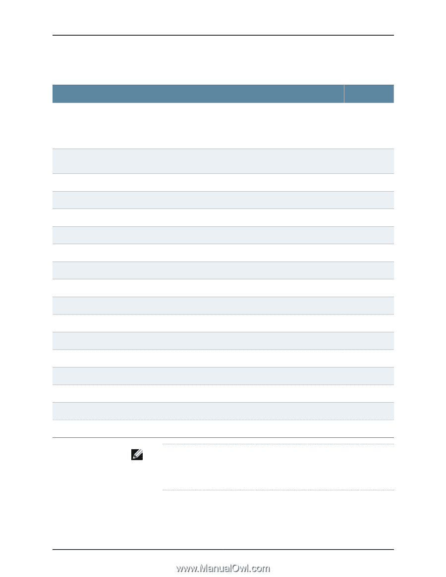
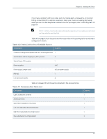
Dell PowerConnect J-Series J-EX8208 Ethernet Switch Hardware Guide Table 41: Accessory Box Parts List (continued) Component Quantity Screws to connect the front pieces and rear pieces of the adjustable mounting brackets for four-post rack 12 installation. Each bracket consists of a front piece and a rear piece. Six screws connect the front-and-rear pieces of each of the two adjustable mounting brackets. Cage nuts for a round-hole rack (clip nuts), #10-32, 0.375-in.(9.525-mm), for mounting the switch in a rack 40 or cabinet Cage nuts for a square-hole rack, #10-32, 0.375-in. (9.525-mm), for mounting the switch in a rack or cabinet 40 Phillips pan-head screws, #10-32 x 5/8-in (15.8-mm), for mounting the switch in a rack or cabinet 40 Phillips pan-head screws, #12-24 x 1/2-in. (12.7-mm), for mounting the switch in a rack or cabinet 40 Washers, #10, for mounting the switch in a rack or cabinet 40 Power cord tray 1 Velcro tie-wraps for power cord tray 12 Power cord retainers 6 Dell PowerConnect Safety, Environmental, and Regulatory Information 1 End User License Agreement 1 DellPowerConnect Warranty and Support Information 1 Registration and Software Updates for Your Dell PowerConnect J-Series Product 1 Open Source Code Notice 1 Ethernet cable, RJ-45/RJ-45, 4-pair stranded UTP, category #5 1 RJ-45 to female DB-9 cable, to connect to the switch's console port using a management PC's serial port 1 ESD grounding strap 1 NOTE: For four-post rack installation, if you install the optional power cord tray you must provide 4 mounting screws-plus 4 cage nuts and washers-that are appropriate for your rack or cabinet. Related • Unpacking a J-EX8200 Switch on page 90 Documentation • J-EX8208 Switch Hardware Overview on page 3 94
-
 1
1 -
2
-
3
-
4
-
5
-
6
-
7
-
8
-
9
-
10
-
11
-
12
-
13
-
14
-
15
-
16
-
17
-
18
-
19
-
20
-
21
-
22
-
23
-
24
-
25
-
26
-
27
-
28
-
29
-
30
-
31
-
32
-
33
-
34
-
35
-
36
-
37
-
38
-
39
-
40
-
41
-
42
-
43
-
44
-
45
-
46
-
47
-
48
-
49
-
50
-
51
-
52
-
53
-
54
-
55
-
56
-
57
-
58
-
59
-
60
-
61
-
62
-
63
-
64
-
65
-
66
-
67
-
68
-
69
-
70
-
71
-
72
-
73
-
74
-
75
-
76
-
77
-
78
-
79
-
80
-
81
-
82
-
83
-
84
-
85
-
86
-
87
-
88
-
89
-
90
-
91
-
92
-
93
-
94
-
95
-
96
-
97
-
98
-
99
-
100
-
101
-
102
-
103
-
104
-
 105
105 -
 106
106 -
 107
107 -
 108
108 -
 109
109 -
 110
110 -
 111
111 -
 112
112 -
 113
113 -
 114
114 -
 115
115 -
116
-
117
-
118
-
119
-
120
-
121
-
122
-
123
-
124
-
125
-
126
-
127
-
128
-
129
-
130
-
131
-
132
-
133
-
134
-
135
-
136
-
137
-
138
-
139
-
140
-
141
-
142
-
143
-
144
-
145
-
146
-
147
-
148
-
149
-
150
-
151
-
152
-
153
-
154
-
155
-
156
-
157
-
158
-
159
-
160
-
161
-
162
-
163
-
164
-
165
-
166
-
167
-
168
-
169
-
170
-
171
-
172
-
173
-
174
-
175
-
176
-
177
-
178
-
179
-
180
-
181
-
182
-
183
-
184
-
185
-
186
-
187
-
188
-
189
-
190
-
191
-
192
-
193
-
194
-
195
-
196
-
197
-
198
-
199
-
200
-
201
-
202
-
203
-
204
-
205
-
206
-
207
-
208
-
209
-
210
-
211
-
212
-
213
-
214
-
215
-
216
-
217
-
218
-
219
-
220
-
221
-
222
-
223
-
224
-
225
-
226
-
227
-
228
-
229
-
230
-
231
-
232
-
233
-
234
-
235
-
236
-
237
-
238
-
239
-
240
-
241
-
242
-
243
-
244
-
245
-
246
-
247
-
248
-
249
-
250
-
251
-
252
-
253
-
254
-
255
-
256
-
257
-
258
-
259
-
260
-
261
-
262
-
263
-
264
-
265
-
266
-
267
-
268
-
269
-
270
-
271
-
272
-
273
-
274
-
275
-
276
 |
 |