Dell PowerConnect J-8208 Hardware Guide - Page 111
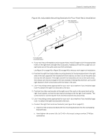
Installing Adjustable Mounting Brackets in a Rack or Cabinet for a J-EX8200 Switch, nonthreaded holes
 |
View all Dell PowerConnect J-8208 manuals
Add to My Manuals
Save this manual to your list of manuals |
Page 111 highlights
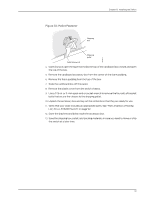
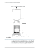
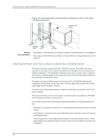
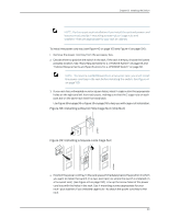
Chapter 8: Installing the Switch Installing Adjustable Mounting Brackets in a Rack or Cabinet for a J-EX8200 Switch To mount the switch on a four-post rack or cabinet, you must first install the adjustable mounting brackets in the rack or cabinet. (The remainder of this topic uses "rack" to mean "rack or cabinet.") The J-EX8200 switch comes with a four-piece set of adjustable mounting brackets that supports the chassis in the rack. NOTE: The adjustable mounting brackets are not for installation in two-post racks. The four adjustable mounting bracket pieces are: • 1 left front adjustable mounting bracket. The bracket is labeled "LEFT FRONT" on the side of the bracket that faces the interior of the rack, near the holes for attaching the bracket to the rack. • 1 right front adjustable mounting bracket. The bracket is labeled "RIGHT FRONT" on the side of the bracket that faces the interior of the rack, near the holes for attaching the bracket to the rack. • 2 rear adjustable mounting brackets. These brackets are labeled "REAR" on the side of the bracket that faces the interior of the rack, near the holes for attaching the bracket to the rack. The rear brackets are interchangeable; you can use either of the rear brackets with the right or left front adjustable mounting bracket. Ensure that you have the following parts and tools available to install the adjustable mounting brackets: • A Phillips (+) screwdriver, number 1, 2, or 3, depending on the size of your rack mounting screws • A Phillips (+) screwdriver, number 2 to install the screws that connect the rear and front mounting brackets • A flat-blade (-) screwdriver if you are installing the switch in a rack with square, nonthreaded holes • 16 screws-and 16 cage nuts and washers if your rack requires them-of the appropriate size to attach the four mounting bracket pieces to the rack When you install the adjustable mounting brackets, the "arms" of the brackets overlap. The overlap area adjusts the total bracket length to fit three standard rack sizes: 23.62 in. (600 mm), 30 in. (762 mm), and 31.5 in. (800 mm). To install the mounting brackets in a four-post rack (see Figure 37 on page 98): 1. Remove the adjustable mounting brackets from the accessory box. 2. Decide where to position the switch in the rack. If the rack is empty, position the switch in the lowest possible location. See "Rack Requirements for a J-EX8208 Switch" on 95
-
 1
1 -
2
-
3
-
4
-
5
-
6
-
7
-
8
-
9
-
10
-
11
-
12
-
13
-
14
-
15
-
16
-
17
-
18
-
19
-
20
-
21
-
22
-
23
-
24
-
25
-
26
-
27
-
28
-
29
-
30
-
31
-
32
-
33
-
34
-
35
-
36
-
37
-
38
-
39
-
40
-
41
-
42
-
43
-
44
-
45
-
46
-
47
-
48
-
49
-
50
-
51
-
52
-
53
-
54
-
55
-
56
-
57
-
58
-
59
-
60
-
61
-
62
-
63
-
64
-
65
-
66
-
67
-
68
-
69
-
70
-
71
-
72
-
73
-
74
-
75
-
76
-
77
-
78
-
79
-
80
-
81
-
82
-
83
-
84
-
85
-
86
-
87
-
88
-
89
-
90
-
91
-
92
-
93
-
94
-
95
-
96
-
97
-
98
-
99
-
100
-
101
-
102
-
103
-
104
-
105
-
 106
106 -
 107
107 -
 108
108 -
 109
109 -
 110
110 -
 111
111 -
 112
112 -
 113
113 -
 114
114 -
 115
115 -
 116
116 -
117
-
118
-
119
-
120
-
121
-
122
-
123
-
124
-
125
-
126
-
127
-
128
-
129
-
130
-
131
-
132
-
133
-
134
-
135
-
136
-
137
-
138
-
139
-
140
-
141
-
142
-
143
-
144
-
145
-
146
-
147
-
148
-
149
-
150
-
151
-
152
-
153
-
154
-
155
-
156
-
157
-
158
-
159
-
160
-
161
-
162
-
163
-
164
-
165
-
166
-
167
-
168
-
169
-
170
-
171
-
172
-
173
-
174
-
175
-
176
-
177
-
178
-
179
-
180
-
181
-
182
-
183
-
184
-
185
-
186
-
187
-
188
-
189
-
190
-
191
-
192
-
193
-
194
-
195
-
196
-
197
-
198
-
199
-
200
-
201
-
202
-
203
-
204
-
205
-
206
-
207
-
208
-
209
-
210
-
211
-
212
-
213
-
214
-
215
-
216
-
217
-
218
-
219
-
220
-
221
-
222
-
223
-
224
-
225
-
226
-
227
-
228
-
229
-
230
-
231
-
232
-
233
-
234
-
235
-
236
-
237
-
238
-
239
-
240
-
241
-
242
-
243
-
244
-
245
-
246
-
247
-
248
-
249
-
250
-
251
-
252
-
253
-
254
-
255
-
256
-
257
-
258
-
259
-
260
-
261
-
262
-
263
-
264
-
265
-
266
-
267
-
268
-
269
-
270
-
271
-
272
-
273
-
274
-
275
-
276
 |
 |