Dell PowerConnect J-8208 Hardware Guide - Page 115
Installing a Round-Hole Cage Nut Clip Nut
 |
View all Dell PowerConnect J-8208 manuals
Add to My Manuals
Save this manual to your list of manuals |
Page 115 highlights
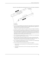
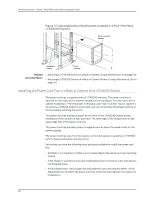
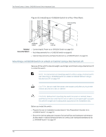
Chapter 8: Installing the Switch NOTE: For four-post rack installation, if you install the optional power cord tray you must provide 4 mounting screws-plus 4 cage nuts and washers-that are appropriate for your rack or cabinet. To install the power cord tray (see Figure 40 on page 100 and Figure 41 on page 100): 1. Remove the power cord tray from the accessory box. 2. Decide where to position the switch in the rack. If the rack is empty, choose the lowest possible location. See "Rack Requirements for a J-EX8208 Switch" on page 63 and "Cabinet Requirements and Specifications for a J-EX8208 Switch" on page 66. NOTE: To mount a J-EX8208 switch on a two-post rack, you must install the power cord tray in the rack before installing the switch. See Figure 41 on page 100. 3. If your rack has unthreaded round or square holes, install 4 cage nuts in the appropriate holes on the right and left front rack posts, making sure that the 2 cage nuts on each post are on the same rack level front and back. Use Figure 38 on page 99 or Figure 39 on page 99 to help you with cage-nut installation. Figure 38: Installing a Round-Hole Cage Nut (Clip Nut) Figure 39: Installing a Square-Hole Cage Nut 4. Position the power cord tray in the rack space immediately below the position in which you want to install the switch (in a two-post rack) or where the switch is installed (in a four-post rack) (see Figure 40 on page 100). Line up the screw holes of the power cord tray with the holes in the rack. Use 4 mounting screws appropriate for your rack-plus washers if you installed cage nuts-to attach the power cord tray to the rack. 99 g040637 g040639
-
 1
1 -
2
-
3
-
4
-
5
-
6
-
7
-
8
-
9
-
10
-
11
-
12
-
13
-
14
-
15
-
16
-
17
-
18
-
19
-
20
-
21
-
22
-
23
-
24
-
25
-
26
-
27
-
28
-
29
-
30
-
31
-
32
-
33
-
34
-
35
-
36
-
37
-
38
-
39
-
40
-
41
-
42
-
43
-
44
-
45
-
46
-
47
-
48
-
49
-
50
-
51
-
52
-
53
-
54
-
55
-
56
-
57
-
58
-
59
-
60
-
61
-
62
-
63
-
64
-
65
-
66
-
67
-
68
-
69
-
70
-
71
-
72
-
73
-
74
-
75
-
76
-
77
-
78
-
79
-
80
-
81
-
82
-
83
-
84
-
85
-
86
-
87
-
88
-
89
-
90
-
91
-
92
-
93
-
94
-
95
-
96
-
97
-
98
-
99
-
100
-
101
-
102
-
103
-
104
-
105
-
106
-
107
-
108
-
109
-
 110
110 -
 111
111 -
 112
112 -
 113
113 -
 114
114 -
 115
115 -
 116
116 -
 117
117 -
 118
118 -
 119
119 -
 120
120 -
121
-
122
-
123
-
124
-
125
-
126
-
127
-
128
-
129
-
130
-
131
-
132
-
133
-
134
-
135
-
136
-
137
-
138
-
139
-
140
-
141
-
142
-
143
-
144
-
145
-
146
-
147
-
148
-
149
-
150
-
151
-
152
-
153
-
154
-
155
-
156
-
157
-
158
-
159
-
160
-
161
-
162
-
163
-
164
-
165
-
166
-
167
-
168
-
169
-
170
-
171
-
172
-
173
-
174
-
175
-
176
-
177
-
178
-
179
-
180
-
181
-
182
-
183
-
184
-
185
-
186
-
187
-
188
-
189
-
190
-
191
-
192
-
193
-
194
-
195
-
196
-
197
-
198
-
199
-
200
-
201
-
202
-
203
-
204
-
205
-
206
-
207
-
208
-
209
-
210
-
211
-
212
-
213
-
214
-
215
-
216
-
217
-
218
-
219
-
220
-
221
-
222
-
223
-
224
-
225
-
226
-
227
-
228
-
229
-
230
-
231
-
232
-
233
-
234
-
235
-
236
-
237
-
238
-
239
-
240
-
241
-
242
-
243
-
244
-
245
-
246
-
247
-
248
-
249
-
250
-
251
-
252
-
253
-
254
-
255
-
256
-
257
-
258
-
259
-
260
-
261
-
262
-
263
-
264
-
265
-
266
-
267
-
268
-
269
-
270
-
271
-
272
-
273
-
274
-
275
-
276
 |
 |
