Dell PowerConnect J-8208 Hardware Guide - Page 131
Power supplies can be installed in any slot. You do not have to, source outlet.
 |
View all Dell PowerConnect J-8208 manuals
Add to My Manuals
Save this manual to your list of manuals |
Page 131 highlights
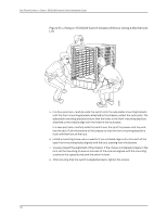
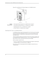
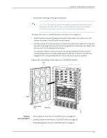
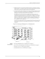
Chapter 9: Installing Switch Components NOTE: Each AC power supply must be connected to a dedicated AC power source outlet. To install an AC power supply in a J-EX8200 switch (see Figure 54 on page 116): 1. Attach the electrostatic discharge (ESD) grounding strap to your bare wrist, and connect the strap to the ESD point on the chassis. 2. If the power supply slot has a cover panel on it, unscrew the screw on the side of the cover panel in the counterclockwise direction using the Phillips (+) screwdriver, number 1, and remove the cover panel. Save the cover panel for later use. 3. Taking care not to touch power supply components, pins, leads, or solder connections, remove the power supply from its bag. 4. Flip the Enable switch next to the appliance inlet on the power supply to the Standby position. 5. Unscrew the captive screw in the counterclockwise direction using the Phillips (+) screwdriver, number 1. 6. Pull the captive screw away from the faceplate of the power supply to release the latch. 7. Pull the handle away from the faceplate of the power supply until it is perpendicular to the faceplate. NOTE: Power supplies can be installed in any slot. You do not have to install the power supplies in serial order. 8. Using both hands, place the power supply in the power supply slot on the front of the switch. Slide the power supply straight into the chassis until the power supply is fully seated in the slot. Ensure the power supply faceplate is flush with any adjacent power supply faceplates or power supply cover panels. 9. Push the handle towards the faceplate of the power supply until it is flush against the faceplate. 10. Push the captive screw into the power supply faceplate. Ensure that the screw is seated inside the corresponding hole on the faceplate. 11. Tighten the captive screw by turning it clockwise using the Phillips (+) screwdriver, number 1. When the screw is completely tight, the latch locks into the switch chassis. 115
-
 1
1 -
2
-
3
-
4
-
5
-
6
-
7
-
8
-
9
-
10
-
11
-
12
-
13
-
14
-
15
-
16
-
17
-
18
-
19
-
20
-
21
-
22
-
23
-
24
-
25
-
26
-
27
-
28
-
29
-
30
-
31
-
32
-
33
-
34
-
35
-
36
-
37
-
38
-
39
-
40
-
41
-
42
-
43
-
44
-
45
-
46
-
47
-
48
-
49
-
50
-
51
-
52
-
53
-
54
-
55
-
56
-
57
-
58
-
59
-
60
-
61
-
62
-
63
-
64
-
65
-
66
-
67
-
68
-
69
-
70
-
71
-
72
-
73
-
74
-
75
-
76
-
77
-
78
-
79
-
80
-
81
-
82
-
83
-
84
-
85
-
86
-
87
-
88
-
89
-
90
-
91
-
92
-
93
-
94
-
95
-
96
-
97
-
98
-
99
-
100
-
101
-
102
-
103
-
104
-
105
-
106
-
107
-
108
-
109
-
110
-
111
-
112
-
113
-
114
-
115
-
116
-
117
-
118
-
119
-
120
-
121
-
122
-
123
-
124
-
125
-
 126
126 -
 127
127 -
 128
128 -
 129
129 -
 130
130 -
 131
131 -
 132
132 -
 133
133 -
 134
134 -
 135
135 -
 136
136 -
137
-
138
-
139
-
140
-
141
-
142
-
143
-
144
-
145
-
146
-
147
-
148
-
149
-
150
-
151
-
152
-
153
-
154
-
155
-
156
-
157
-
158
-
159
-
160
-
161
-
162
-
163
-
164
-
165
-
166
-
167
-
168
-
169
-
170
-
171
-
172
-
173
-
174
-
175
-
176
-
177
-
178
-
179
-
180
-
181
-
182
-
183
-
184
-
185
-
186
-
187
-
188
-
189
-
190
-
191
-
192
-
193
-
194
-
195
-
196
-
197
-
198
-
199
-
200
-
201
-
202
-
203
-
204
-
205
-
206
-
207
-
208
-
209
-
210
-
211
-
212
-
213
-
214
-
215
-
216
-
217
-
218
-
219
-
220
-
221
-
222
-
223
-
224
-
225
-
226
-
227
-
228
-
229
-
230
-
231
-
232
-
233
-
234
-
235
-
236
-
237
-
238
-
239
-
240
-
241
-
242
-
243
-
244
-
245
-
246
-
247
-
248
-
249
-
250
-
251
-
252
-
253
-
254
-
255
-
256
-
257
-
258
-
259
-
260
-
261
-
262
-
263
-
264
-
265
-
266
-
267
-
268
-
269
-
270
-
271
-
272
-
273
-
274
-
275
-
276
 |
 |