Dell PowerConnect J-8208 Hardware Guide - Page 150
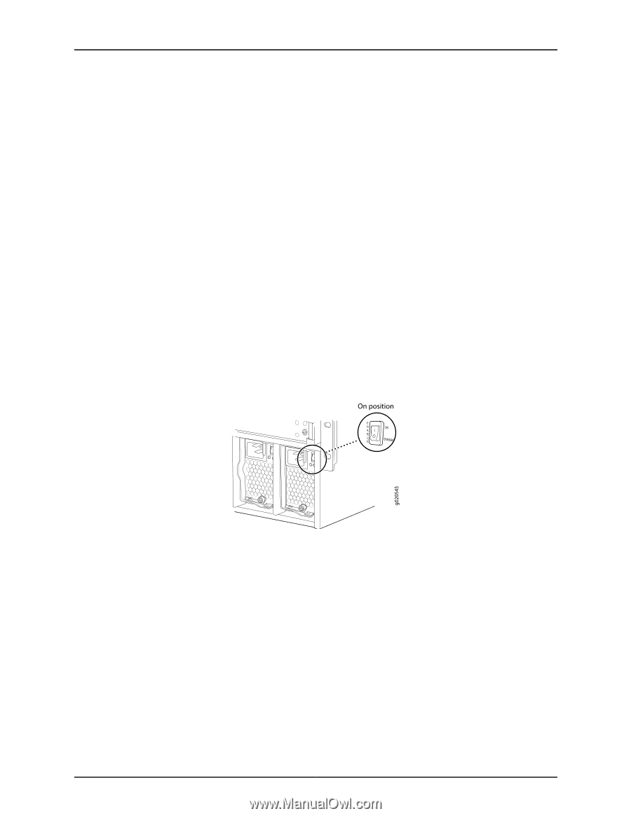
Flip the Enable Switch to the ON position, Enable, INPUT OK, IN OK, OUTPUT OK, OUT OK
 |
View all Dell PowerConnect J-8208 manuals
Add to My Manuals
Save this manual to your list of manuals |
Page 150 highlights
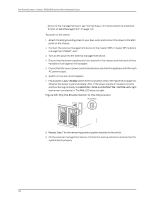
Dell PowerConnect J-Series J-EX8208 Ethernet Switch Hardware Guide device to the management port, see "Connecting a J-EX Series Switch to a Network for Out-of-Band Management" on page 140. To power on the switch: 1. Attach the ESD grounding strap to your bare wrist and connect the strap to the ESD point on the chassis. 2. Connect the external management device to the master SRE or master RE module's management (MGMT) port. 3. Turn on the power to the external management device. 4. Ensure that the power supplies are fully inserted in the chassis and that each of their handles is flush against the faceplate. 5. Ensure that the source power cord is inserted securely into the appliance inlet for each AC power supply. 6. Switch on the site circuit breakers. 7. Flip a power supply's Enable switch to the on position (ON). See Figure 66 on page 134. Observe the power supply faceplate LEDs. If the power supply is installed correctly and functioning normally, the INPUT OK / IN OK and OUTPUT OK / OUT OK LEDs light and remain constantly lit. The FAIL LED does not light. Figure 66: Flip the Enable Switch to the ON position 8. Repeat Step 7 for the remaining power supplies installed in the switch. 9. On the external management device, monitor the startup process to ensure that the system boots properly. 134
-
 1
1 -
2
-
3
-
4
-
5
-
6
-
7
-
8
-
9
-
10
-
11
-
12
-
13
-
14
-
15
-
16
-
17
-
18
-
19
-
20
-
21
-
22
-
23
-
24
-
25
-
26
-
27
-
28
-
29
-
30
-
31
-
32
-
33
-
34
-
35
-
36
-
37
-
38
-
39
-
40
-
41
-
42
-
43
-
44
-
45
-
46
-
47
-
48
-
49
-
50
-
51
-
52
-
53
-
54
-
55
-
56
-
57
-
58
-
59
-
60
-
61
-
62
-
63
-
64
-
65
-
66
-
67
-
68
-
69
-
70
-
71
-
72
-
73
-
74
-
75
-
76
-
77
-
78
-
79
-
80
-
81
-
82
-
83
-
84
-
85
-
86
-
87
-
88
-
89
-
90
-
91
-
92
-
93
-
94
-
95
-
96
-
97
-
98
-
99
-
100
-
101
-
102
-
103
-
104
-
105
-
106
-
107
-
108
-
109
-
110
-
111
-
112
-
113
-
114
-
115
-
116
-
117
-
118
-
119
-
120
-
121
-
122
-
123
-
124
-
125
-
126
-
127
-
128
-
129
-
130
-
131
-
132
-
133
-
134
-
135
-
136
-
137
-
138
-
139
-
140
-
141
-
142
-
143
-
144
-
 145
145 -
 146
146 -
 147
147 -
 148
148 -
 149
149 -
 150
150 -
 151
151 -
 152
152 -
 153
153 -
 154
154 -
 155
155 -
156
-
157
-
158
-
159
-
160
-
161
-
162
-
163
-
164
-
165
-
166
-
167
-
168
-
169
-
170
-
171
-
172
-
173
-
174
-
175
-
176
-
177
-
178
-
179
-
180
-
181
-
182
-
183
-
184
-
185
-
186
-
187
-
188
-
189
-
190
-
191
-
192
-
193
-
194
-
195
-
196
-
197
-
198
-
199
-
200
-
201
-
202
-
203
-
204
-
205
-
206
-
207
-
208
-
209
-
210
-
211
-
212
-
213
-
214
-
215
-
216
-
217
-
218
-
219
-
220
-
221
-
222
-
223
-
224
-
225
-
226
-
227
-
228
-
229
-
230
-
231
-
232
-
233
-
234
-
235
-
236
-
237
-
238
-
239
-
240
-
241
-
242
-
243
-
244
-
245
-
246
-
247
-
248
-
249
-
250
-
251
-
252
-
253
-
254
-
255
-
256
-
257
-
258
-
259
-
260
-
261
-
262
-
263
-
264
-
265
-
266
-
267
-
268
-
269
-
270
-
271
-
272
-
273
-
274
-
275
-
276
 |
 |