Dell PowerConnect J-8208 Hardware Guide - Page 125
Installing a Round-Hole Cage Nut Clip Nut, Installing a Square-Hole Cage Nut
 |
View all Dell PowerConnect J-8208 manuals
Add to My Manuals
Save this manual to your list of manuals |
Page 125 highlights
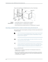
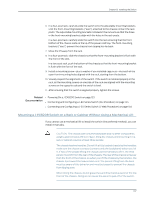
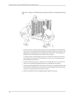
g040637 Chapter 8: Installing the Switch To install the switch in the rack or cabinet (see Figure 52 on page 111 and Figure 53 on page 111): CAUTION: If you are installing more than one switch in a rack or cabinet, install the first one at the bottom of the rack. Do not attempt to install a switch manually in an upper position in a rack or cabinet. 1. Ensure that the rack or cabinet is placed in its permanent location and is secured to the building. 2. If your rack has unthreaded round or square holes, ensure that 24 cage nuts are installed in the appropriate holes on the left front and right front rack posts, so that the 12 cage nuts on each post are on the same rack level front and back. Use Figure 49 on page 109 or Figure 50 on page 109 to help you with cage-nut installation. Figure 49: Installing a Round-Hole Cage Nut (Clip Nut) Figure 50: Installing a Square-Hole Cage Nut 3. Position the switch in front of the rack or cabinet, centering it in front of the adjustable mounting brackets. Use a pallet jack if one is available. 4. With one person on each side and one person in the rear, hold the bottom of the chassis and carefully lift it onto the adjustable mounting brackets installed in a four-post rack or onto the power cord tray installed in a two-post rack. See Figure 51 on page 110. WARNING: To prevent injury, keep your back straight and lift with your legs, not your back. Do not twist your body as you lift. Balance the load evenly and be sure that your footing is firm. 109 g040639
-
 1
1 -
2
-
3
-
4
-
5
-
6
-
7
-
8
-
9
-
10
-
11
-
12
-
13
-
14
-
15
-
16
-
17
-
18
-
19
-
20
-
21
-
22
-
23
-
24
-
25
-
26
-
27
-
28
-
29
-
30
-
31
-
32
-
33
-
34
-
35
-
36
-
37
-
38
-
39
-
40
-
41
-
42
-
43
-
44
-
45
-
46
-
47
-
48
-
49
-
50
-
51
-
52
-
53
-
54
-
55
-
56
-
57
-
58
-
59
-
60
-
61
-
62
-
63
-
64
-
65
-
66
-
67
-
68
-
69
-
70
-
71
-
72
-
73
-
74
-
75
-
76
-
77
-
78
-
79
-
80
-
81
-
82
-
83
-
84
-
85
-
86
-
87
-
88
-
89
-
90
-
91
-
92
-
93
-
94
-
95
-
96
-
97
-
98
-
99
-
100
-
101
-
102
-
103
-
104
-
105
-
106
-
107
-
108
-
109
-
110
-
111
-
112
-
113
-
114
-
115
-
116
-
117
-
118
-
119
-
 120
120 -
 121
121 -
 122
122 -
 123
123 -
 124
124 -
 125
125 -
 126
126 -
 127
127 -
 128
128 -
 129
129 -
 130
130 -
131
-
132
-
133
-
134
-
135
-
136
-
137
-
138
-
139
-
140
-
141
-
142
-
143
-
144
-
145
-
146
-
147
-
148
-
149
-
150
-
151
-
152
-
153
-
154
-
155
-
156
-
157
-
158
-
159
-
160
-
161
-
162
-
163
-
164
-
165
-
166
-
167
-
168
-
169
-
170
-
171
-
172
-
173
-
174
-
175
-
176
-
177
-
178
-
179
-
180
-
181
-
182
-
183
-
184
-
185
-
186
-
187
-
188
-
189
-
190
-
191
-
192
-
193
-
194
-
195
-
196
-
197
-
198
-
199
-
200
-
201
-
202
-
203
-
204
-
205
-
206
-
207
-
208
-
209
-
210
-
211
-
212
-
213
-
214
-
215
-
216
-
217
-
218
-
219
-
220
-
221
-
222
-
223
-
224
-
225
-
226
-
227
-
228
-
229
-
230
-
231
-
232
-
233
-
234
-
235
-
236
-
237
-
238
-
239
-
240
-
241
-
242
-
243
-
244
-
245
-
246
-
247
-
248
-
249
-
250
-
251
-
252
-
253
-
254
-
255
-
256
-
257
-
258
-
259
-
260
-
261
-
262
-
263
-
264
-
265
-
266
-
267
-
268
-
269
-
270
-
271
-
272
-
273
-
274
-
275
-
276
 |
 |