Dell PowerConnect J-8208 Hardware Guide - Page 141
Installing a Transceiver in a J-EX Series Switch
 |
View all Dell PowerConnect J-8208 manuals
Add to My Manuals
Save this manual to your list of manuals |
Page 141 highlights
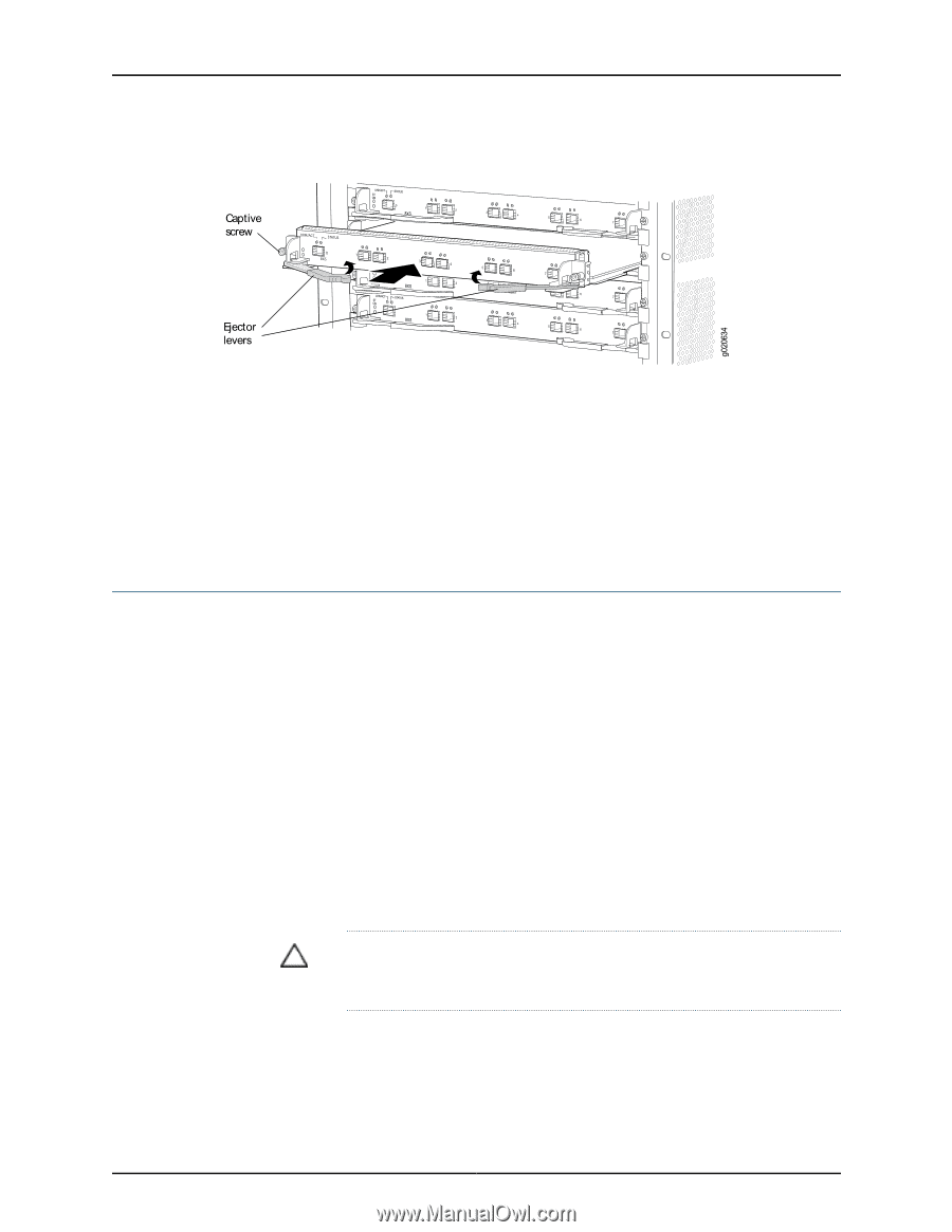
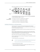
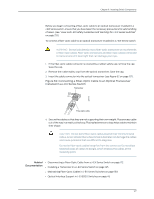
Chapter 9: Installing Switch Components Figure 60: Installing a Line Card in a J-EX8200 Switch Chassis You can verify that the line card is functioning correctly by issuing the show chassis fpc and show chassis fpc pic-status commands. Related • Removing a Line Card from a J-EX8200 Switch on page 170 Documentation • 8-port SFP+ Line Card in a J-EX8200 Switch on page 27 • 48-port SFP Line Card in a J-EX8200 Switch on page 28 • 48-port RJ-45 Line Card in a J-EX8200 Switch on page 29 Installing a Transceiver in a J-EX Series Switch The transceivers for J-EX Series switches are hot-removable and hot-insertable field-replaceable units (FRUs): You can remove and replace them without powering off the switch or disrupting switch functions. Use only optical transceivers and optical connectors purchased from Dell for your J-EX Series switch. Before you begin installing a transceiver in a J-EX Series switch, ensure that you have taken the necessary precautions for safe handling of lasers (see "Laser and LED Safety Guidelines and Warnings for J-EX Series Switches" on page 213). Ensure that you have a rubber safety cap available to cover the transceiver. Figure 61 on page 126 shows how to install an SFP transceiver. The procedure is the same for all transceiver types. To install a transceiver in a J-EX Series switch: CAUTION: To avoid electrostatic discharge (ESD) damage to the transceiver, do not touch the connector pins at the end of the transceiver. 1. Remove the transceiver from its bag. 2. Check to see whether the transceiver is covered by a rubber safety cap. If it is not, cover the transceiver with a rubber safety cap. 125
-
 1
1 -
2
-
3
-
4
-
5
-
6
-
7
-
8
-
9
-
10
-
11
-
12
-
13
-
14
-
15
-
16
-
17
-
18
-
19
-
20
-
21
-
22
-
23
-
24
-
25
-
26
-
27
-
28
-
29
-
30
-
31
-
32
-
33
-
34
-
35
-
36
-
37
-
38
-
39
-
40
-
41
-
42
-
43
-
44
-
45
-
46
-
47
-
48
-
49
-
50
-
51
-
52
-
53
-
54
-
55
-
56
-
57
-
58
-
59
-
60
-
61
-
62
-
63
-
64
-
65
-
66
-
67
-
68
-
69
-
70
-
71
-
72
-
73
-
74
-
75
-
76
-
77
-
78
-
79
-
80
-
81
-
82
-
83
-
84
-
85
-
86
-
87
-
88
-
89
-
90
-
91
-
92
-
93
-
94
-
95
-
96
-
97
-
98
-
99
-
100
-
101
-
102
-
103
-
104
-
105
-
106
-
107
-
108
-
109
-
110
-
111
-
112
-
113
-
114
-
115
-
116
-
117
-
118
-
119
-
120
-
121
-
122
-
123
-
124
-
125
-
126
-
127
-
128
-
129
-
130
-
131
-
132
-
133
-
134
-
135
-
 136
136 -
 137
137 -
 138
138 -
 139
139 -
 140
140 -
 141
141 -
 142
142 -
 143
143 -
 144
144 -
 145
145 -
 146
146 -
147
-
148
-
149
-
150
-
151
-
152
-
153
-
154
-
155
-
156
-
157
-
158
-
159
-
160
-
161
-
162
-
163
-
164
-
165
-
166
-
167
-
168
-
169
-
170
-
171
-
172
-
173
-
174
-
175
-
176
-
177
-
178
-
179
-
180
-
181
-
182
-
183
-
184
-
185
-
186
-
187
-
188
-
189
-
190
-
191
-
192
-
193
-
194
-
195
-
196
-
197
-
198
-
199
-
200
-
201
-
202
-
203
-
204
-
205
-
206
-
207
-
208
-
209
-
210
-
211
-
212
-
213
-
214
-
215
-
216
-
217
-
218
-
219
-
220
-
221
-
222
-
223
-
224
-
225
-
226
-
227
-
228
-
229
-
230
-
231
-
232
-
233
-
234
-
235
-
236
-
237
-
238
-
239
-
240
-
241
-
242
-
243
-
244
-
245
-
246
-
247
-
248
-
249
-
250
-
251
-
252
-
253
-
254
-
255
-
256
-
257
-
258
-
259
-
260
-
261
-
262
-
263
-
264
-
265
-
266
-
267
-
268
-
269
-
270
-
271
-
272
-
273
-
274
-
275
-
276
 |
 |