Dell PowerConnect J-8208 Hardware Guide - Page 134
Installing an SRE Module in a J-EX8208 Switch, Discharge Damage on J-EX Series Switches
 |
View all Dell PowerConnect J-8208 manuals
Add to My Manuals
Save this manual to your list of manuals |
Page 134 highlights
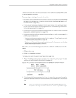
Dell PowerConnect J-Series J-EX8208 Ethernet Switch Hardware Guide Installing an SRE Module in a J-EX8208 Switch You can install either one or two Switch Fabric and Routing Engine (SRE) modules in a J-EX8208 switch. The SRE modules install horizontally in the front of the chassis in the slots labeled SRE0 and SRE1. NOTE: We recommend that you install two SRE modules for redundancy. If you install only one SRE module, we recommend that you install it in the slot SRE0. CAUTION: Do not lift the SRE module by holding the ejector levers. The levers cannot support the weight of the module. Lifting the modules by the levers might bend the levers, and the bent levers will prevent the SRE module from being properly seated in the chassis. Before you begin installing an SRE module in a J-EX8208 switch: • Ensure you understand how to prevent ESD damage. See "Prevention of Electrostatic Discharge Damage on J-EX Series Switches" on page 236. Ensure that you have the following parts and tools available to install an SRE module: • Electrostatic discharge (ESD) grounding strap • Phillips (+) screwdriver, number 2 To install an SRE module in a J-EX8208 switch (see Figure 56 on page 119): 1. Attach the electrostatic discharge (ESD) grounding strap to your bare wrist and connect the strap to one of the ESD points on the chassis. 2. Taking care not to touch the leads, pins, or solder connections, pull the SRE module out from the bag. 3. Pull both the ejector levers outward, away from the faceplate of the SRE module, until they go no further. 4. If the slot has a cover panel on it, unscrew the two screws on either side of the cover panel counterclockwise using the Phillips (+) screwdriver, number 2. Remove the cover panel. Save the cover panel for later use. 5. Carefully align the sides of the SRE module with the guides inside the chassis. 6. Ensuring that the SRE module is correctly aligned, carefully slide it into the chassis until you feel resistance. 7. Push both the ejector levers towards the faceplate of the SRE module until the levers are flush against the faceplate and are fully engaged. 118
-
 1
1 -
2
-
3
-
4
-
5
-
6
-
7
-
8
-
9
-
10
-
11
-
12
-
13
-
14
-
15
-
16
-
17
-
18
-
19
-
20
-
21
-
22
-
23
-
24
-
25
-
26
-
27
-
28
-
29
-
30
-
31
-
32
-
33
-
34
-
35
-
36
-
37
-
38
-
39
-
40
-
41
-
42
-
43
-
44
-
45
-
46
-
47
-
48
-
49
-
50
-
51
-
52
-
53
-
54
-
55
-
56
-
57
-
58
-
59
-
60
-
61
-
62
-
63
-
64
-
65
-
66
-
67
-
68
-
69
-
70
-
71
-
72
-
73
-
74
-
75
-
76
-
77
-
78
-
79
-
80
-
81
-
82
-
83
-
84
-
85
-
86
-
87
-
88
-
89
-
90
-
91
-
92
-
93
-
94
-
95
-
96
-
97
-
98
-
99
-
100
-
101
-
102
-
103
-
104
-
105
-
106
-
107
-
108
-
109
-
110
-
111
-
112
-
113
-
114
-
115
-
116
-
117
-
118
-
119
-
120
-
121
-
122
-
123
-
124
-
125
-
126
-
127
-
128
-
 129
129 -
 130
130 -
 131
131 -
 132
132 -
 133
133 -
 134
134 -
 135
135 -
 136
136 -
 137
137 -
 138
138 -
 139
139 -
140
-
141
-
142
-
143
-
144
-
145
-
146
-
147
-
148
-
149
-
150
-
151
-
152
-
153
-
154
-
155
-
156
-
157
-
158
-
159
-
160
-
161
-
162
-
163
-
164
-
165
-
166
-
167
-
168
-
169
-
170
-
171
-
172
-
173
-
174
-
175
-
176
-
177
-
178
-
179
-
180
-
181
-
182
-
183
-
184
-
185
-
186
-
187
-
188
-
189
-
190
-
191
-
192
-
193
-
194
-
195
-
196
-
197
-
198
-
199
-
200
-
201
-
202
-
203
-
204
-
205
-
206
-
207
-
208
-
209
-
210
-
211
-
212
-
213
-
214
-
215
-
216
-
217
-
218
-
219
-
220
-
221
-
222
-
223
-
224
-
225
-
226
-
227
-
228
-
229
-
230
-
231
-
232
-
233
-
234
-
235
-
236
-
237
-
238
-
239
-
240
-
241
-
242
-
243
-
244
-
245
-
246
-
247
-
248
-
249
-
250
-
251
-
252
-
253
-
254
-
255
-
256
-
257
-
258
-
259
-
260
-
261
-
262
-
263
-
264
-
265
-
266
-
267
-
268
-
269
-
270
-
271
-
272
-
273
-
274
-
275
-
276
 |
 |